What Is Astigmatism, Really? Why Tangential and Sagittal Foci "Go Their Separate Ways"
 11/12 2026
 403

Abstract: Astigmatism is a classic off-axis primary aberration—and the imaging defect the naked eye can spot most easily. At its core, the optical system refracts rays in the tangential plane and the sagittal plane differently, so the two bundles emerging from a single off-axis object point come to focus at different locations, producing two mutually perpendicular focal lines.
It is one of the main culprits behind blurry images and fuzzy text at the edges of AR devices. Among all optical aberrations, astigmatism is the most intuitive and the easiest to notice with the naked eye.
In an ideal optical system, light from a point source passes through a lens and converges to a single sharp point. In an optical path with astigmatism, that perfect point is distorted beyond recognition and splits into two short, perpendicular lines—the tangential focal line and the sagittal focal line.
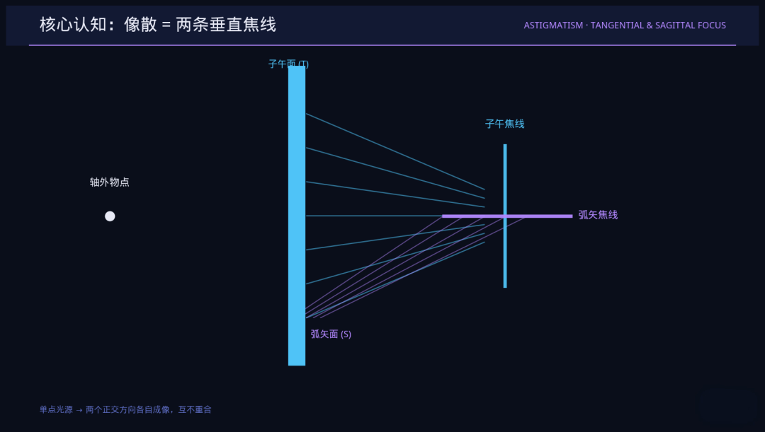
The rays in these two directions converge separately and never meet—that is the defining feature of astigmatism. This article breaks down the underlying mechanism of astigmatism, how it shows up in imaging, and the correction schemes dedicated to AR optical systems.
Key takeaway: Astigmatism is the phenomenon in which the tangential and sagittal image points of a narrow beam from an off-axis object point fail to coincide after passing through an optical system. In essence, the system treats rays in the tangential and sagittal planes differently—unequal refractive power along two orthogonal directions turns a single point source into two perpendicular focal lines. Correcting astigmatism therefore means getting the optical system to balance the optical paths and treat the tangential and sagittal directions equally.
I. The physical essence of astigmatism: the tangential and sagittal planes "part ways"
A narrow beam from an off-axis object point can be decomposed into two mutually perpendicular optical planes: the tangential plane (the reference plane containing the chief ray and the optical axis) and the sagittal plane (the plane orthogonal to it, which also contains the chief ray).
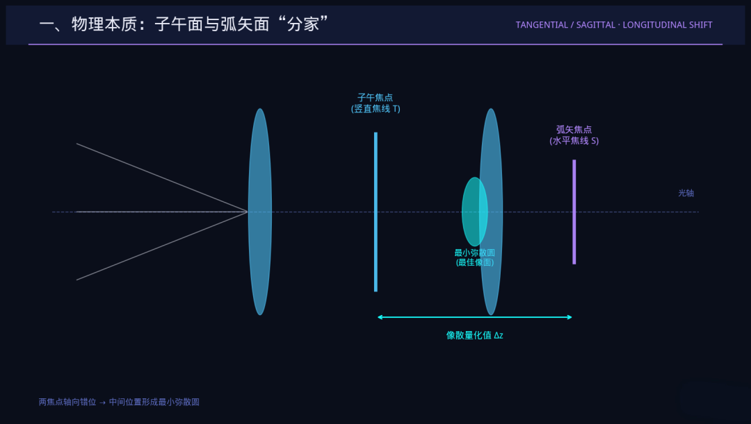
In an ideal optical system, rays in both planes obey the same refraction law and converge to the same image point. Real optical structures, however, inherently bend rays differently in the two planes, which directly offsets the tangential focus and the sagittal focus along the optical axis—and that offset is the quantitative value of astigmatism (usually given as a percentage of focal length or in diopters).
At the tangential focus, the beam appears as a short line running in the sagittal direction; at the sagittal focus, it appears as a short line running in the tangential direction. Under the primary astigmatism approximation, the circle of least confusion sits midway between the two foci and is also the preferred best image plane in conventional optical design.
In short, astigmatism arises because the optical system has unequal refractive power in two orthogonal cross-sections, so rays fail to converge at a single point.
II. How astigmatism manifests in optical systems
Under the primary astigmatism approximation, astigmatism depends only on field size, not on aperture; in large-aperture, wide-field systems, higher-order astigmatism terms introduce an aperture dependence.
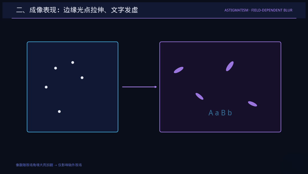
This also means the central field of view suffers no astigmatic interference—and the larger the field angle, the worse the distortion. Its most typical signature is stretched, deformed point sources at the edges. When you photograph the night sky, stars at the corners of the frame show up as radially or tangentially stretched ellipses rather than round points—a direct, visible sign of astigmatism.
In AR optical waveguide devices, astigmatism directly produces hazy images, unclear text, and blurred contours in the edge field of view, seriously undermining visual readability. It is a fundamental aberration that any high-precision AR display design must correct.
III. Correcting astigmatism: from structural symmetry to advanced freeform surfaces
The industry has developed a mature three-tier correction framework that fits different optical design scenarios.
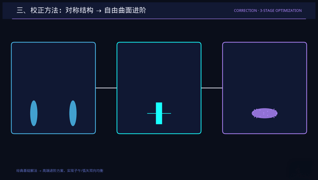
The first tier is correction through symmetric structure, on the same principle as coma correction. A typical example is the double-Gauss lens, whose lens groups are arranged symmetrically about the stop: opposite aberrations from the front and rear groups cancel each other out, and a low incidence angle design also helps weaken astigmatism.
The second tier is optimizing the field stop position. Astigmatism is closely tied to stop position; placing the stop far from the lens group can effectively suppress it. In optical software such as ZEMAX, the ASTI operand allows precise optimization of the astigmatism value.
The third tier is high-end surface design. Aspheric and freeform lenses can precisely regulate the optical paths in both directions. Off-axis reflective AR systems can achieve full-field astigmatism correction through freeform surfaces designed specifically for the purpose.
IV. Astigmatism unique to AR optical waveguides: the extra astigmatism introduced by grating diffraction
In AR diffractive optical waveguides, beyond the usual lens-path deviations, there is another aberration source specific to the technology: grating diffraction.
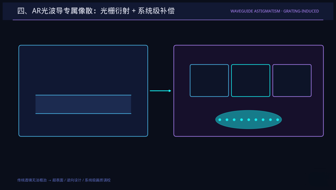
The periodic structure of a diffraction grating usually provides diffractive optical power in only one direction, while rays in the orthogonal direction essentially undergo refractive propagation. As a result, the effective optical power in the tangential and sagittal cross-sections is naturally asymmetric, creating an astigmatic effect much like that of a cylindrical lens.
This grating-induced astigmatism cannot be fundamentally eliminated by traditional spherical or aspheric lenses; it must be compensated at the system level for the waveguide as a whole.
Metasurface technology has now emerged as a core solution. In a 2025 paper in Light: Science & Applications (a Nature portfolio journal), the team of Sun Xiaowei at SUSTech proposed an inversely designed metasurface coupler: R/G/B travel in different diffraction orders, achieving uniform deflection of the three colors and achromatic incoupling within a >45° field of view on a single-layer high-refractive-index waveguide—fundamentally alleviating the dispersion and efficiency shortcomings of traditional gratings.
According to publicly available technical materials from JBD, its mass-production ARTCs image quality correction engine uses system-level pixel-by-pixel tuning to raise the global brightness uniformity of MicroLED optical waveguides from <40% to >80%, and reduce chromatic aberration ΔE from >0.1 to approximately 0.02—greatly improving full-field imaging deviations including astigmatism and uneven brightness.
Conclusion: At bottom, the core problem of astigmatism is the optical system's "differential treatment" of rays in the tangential and sagittal directions.
Correcting astigmatism means achieving a balanced unification of the two optical paths: symmetric structures are the classic, foundational solution; freeform surfaces are the high-end, advanced solution; and metasurface coupling and system-level image quality tuning are new correction paradigms built specifically for AR optical waveguide devices.
Understanding astigmatism means grasping the core cause of edge blurring in AR images. Precise astigmatism correction is a key step for AR devices to move up from basic "can display" to high-definition "can see clearly."
Discussion: In AR optical design, which do you think affects edge-field image quality more—astigmatism or chromatic aberration? Feel free to leave a comment and share your view.
—— AR Andy | Focused on optical waveguides and the AR microdisplay track, providing in-depth analysis of the underlying logic of the optical industry
[Disclaimer] This article is industry optics popular science content. The principles, phenomena, and optimization schemes discussed all come from public optical theory and general optical design experience. It is intended solely for technical learning and industry exchange and does not constitute a basis for product design, process iteration, or mass-production selection.
-
![]()
What Is Astigmatism, Really? Why Tangential and Sagittal Foci "Go Their Separate Ways"
-
![]()
Gree Electric's Performance Weighed Down by Soaring Copper Prices: Will Dong Mingzhu Unveil a "Big Move" by Year-End?
-
![]()
AI R&D Doubles in Speed as Anthropic Redacts Most of a 100-Page Report
-
![]()
Crown New Materials to Inject RMB 228 Million into Zhejiang Optical Film Project
-
![]()
Gaize Technology Officially Announces Takeover of Entire Japanese Optical Powerhouse Plant: Can It Translate Into Production Capacity?
-
![]()
Baidu Begins Building Factories
-
Hong Kong Listed Company Huaxia Culture Technology Enters AI Sector with Mid-Term Profit Alert Exceeding HKD 900 Million
-
![]()
NXP Earnings: Net Income Hits $884 Million as Automotive Chip Growth Lags at 13%