A Ghost Image, an Optical Path — Tracing the Path of Stray Light in AR Waveguides
 11/20 2026
 376
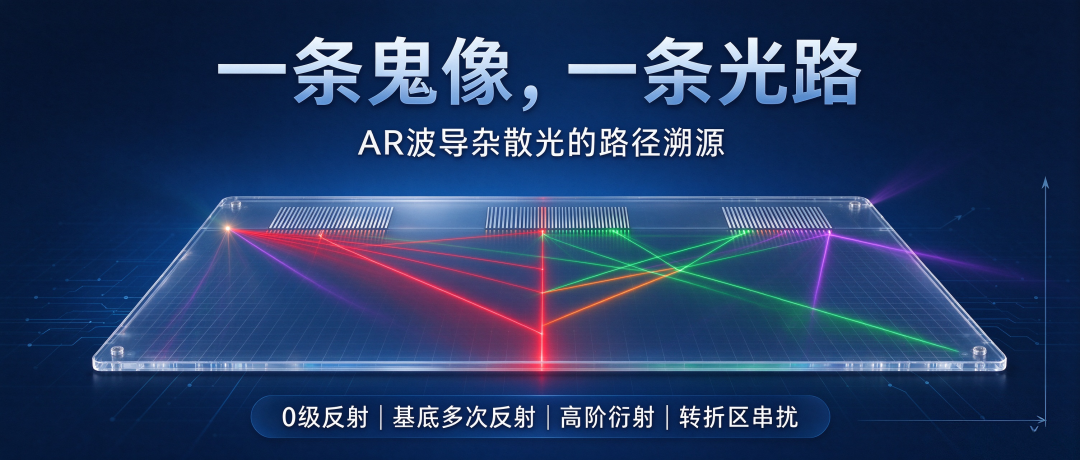
Abstract: Ghost images in AR waveguides are not random stray spots; every double image corresponds to a definite optical path.
This article organizes the four most common ghost image paths, their identifying features, and controlled-variable troubleshooting approaches, helping engineers reverse-locate the root cause from the image and avoid blind trial-and-error tuning.
When debugging AR waveguides, an inexplicable light spot or double image often appears in the picture.
Many people's first reaction is to vaguely call it stray light and then start guessing one by one: did the grating process fail? Is the coating no good? Or was the assembly misaligned? Guessing wastes too much time.
Every ghost image can be traced to a real optical path. Only by understanding how the light travels can you know which parameter to adjust.
Ghost image source 1: 0th-order reflected stray light from the in-coupling grating
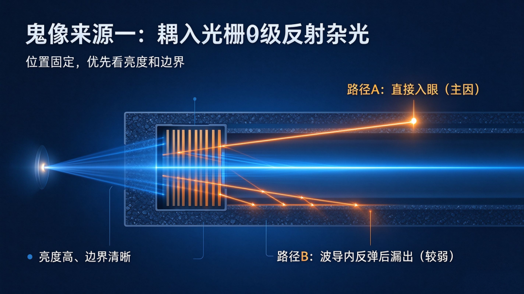
This type is discussed the most, but its optical path is also the easiest to explain incorrectly. The micro-image source strikes the in-coupling grating; part of the light diffracts as designed and successfully enters the waveguide, which is the main optical path we want to use; the rest is 0th-order directly reflected light.
The online claim that "light bounces back to the micro-image source and forms a secondary image" is not the mainstream case. For devices such as MicroOLED and MicroLED, the surface absorption is strong; even if a small amount of light is reflected back, the energy is too low to form a visible double image.
The 0th-order ghost images that can actually be seen have two paths.
One is that the 0th-order reflected light travels directly forward, does not pass through the waveguide, and enters the human eye all the way; this is the main cause, with energy far higher than the other path.
The other is that this beam bounces back and forth between the upper and lower surfaces of the waveguide and finally leaks out from the out-coupling region; although theoretically possible, the round-trip reflection loss is large, so the brightness is usually much weaker.
It has a very conspicuous feature: the relative position of the ghost image and the main image is fixed, and it does not move when the field of view is switched; it is especially obvious in dark-field testing; moreover, its position is not affected by the grating period.
Here is a very practical distinguishing clue from frontline debugging: although both remain stationary in position, the 0th-order ghost image is generally brighter with clean, sharp edges, a short optical path, and low loss; ghost images from multiple substrate reflections are generally darker with blurred edges because of repeated reflections and severe energy attenuation.
Of course, this is only an empirical clue and cannot be used as the sole criterion. If these features match, suspect 0th-order reflection first.
The most reliable engineering solution is to add a light-absorbing structure at the in-coupling end, or use an inclined grating to move the 0th-order light directly out of the eye box.
By the way, a commonly heard solution: using a "1/4 wave plate + polarization management."
The premise for this approach to work is that the incident light is pure linear polarization; it was originally used to suppress light returning along the original path and cannot directly eliminate the 0th-order ghost image.
For the vast majority of unpolarized micro-image sources, its effect is limited, so do not treat it as a universal solution.
Ghost image source 2: unintended multiple reflection paths within the substrate
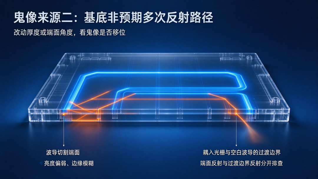
The waveguide substrate itself is a labyrinth of optical paths where light easily gets lost. Ideally, light travels forward only along the predetermined route by total internal reflection.
In reality, light undergoes unexpected reflections at the cut end faces of the waveguide and at the transition boundary between the in-coupling grating and the blank waveguide, deviates from the main optical path, bounces back and forth inside the plate, and finally exits from the wrong position at the out-coupling end, forming a ghost image.
There is a small engineering point to remember here: if the cover plate is bonded with a refractive-index-matching adhesive, the interface reflectance can be suppressed to within 0.1%, so it is generally not the main source of stray light, and there is no need to struggle with this point first. The more reflections there are, the darker the ghost image and the harder its position is to predict.
Troubleshooting is also simple: change the waveguide thickness or adjust the end-face cutting angle. If the ghost image shifts accordingly, and the spot positions fluctuate greatly across different substrate batches, it is basically unintended total internal reflection within the substrate at work.
Ghost image source 3: higher-order grating diffraction causing out-of-field light leakage
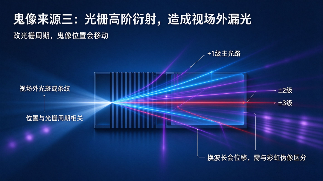
The grating distributes diffraction energy among various orders according to the period and incident conditions. In addition to the required +1 order, higher orders such as ±2 and ±3 are generated simultaneously.
Although part of the higher-order diffracted light successfully couples into the waveguide, its propagation angle deviates from the design window and cannot continuously satisfy total internal reflection, or it exits at the out-coupling end at the wrong angle, finally leaving faint spots or stripes at the edge of the main field of view or even outside it.
It has a key difference from the 0th-order ghost image: the exit direction of higher-order diffraction follows the grating period, so changing the period moves the ghost image; while the direction of 0th-order reflection is unrelated to the grating period.
However, be careful here as well: when changing the light source wavelength, both higher-order diffraction ghost images and rainbow artifacts caused by dispersion will shift, so changing to a monochromatic light source alone cannot settle the matter; it is best to verify together with a grating period scan.
Ghost image source 4: field-of-view crosstalk in the turning region of 2D pupil expansion

2D pupil expansion waveguides rely on two sets of orthogonal gratings to expand the pupil twice and enlarge the exit pupil. This crosstalk is not evenly distributed across the entire out-coupling grating; the high-incidence area is the turning grating region where the two 1D pupil expansion gratings overlap.
If the energy isolation between different fields of view in the turning region is insufficient, light belonging to one field of view will be incorrectly extracted and leak into another field-of-view channel, generating a ghost image.
This type of ghost image is easiest to recognize: it sticks next to the main image and is bound to it. Rotate the field of view or move the main image, and it moves along. Whenever you see "wherever the main image goes, the ghost image follows," prioritize checking the turning grating region of the 2D pupil expansion.
Ghost image tracing: using controlled variables to infer the optical path from position

The four paths above each correspond to a clear set of image features. The whole tracing approach, in plain terms, is controlled-variable testing rather than guessing by feel.
The ghost image position does not change with the field of view, nor does it move when the grating period is changed; brightness is relatively high and the boundary is clear: prioritize it as a 0th-order reflected ghost image.
The ghost image position does not change with the field of view; brightness is relatively weak and edges are blurred; adjusting the waveguide thickness or end-face angle shifts the spot: unintended multiple reflections within the substrate.
Changing the grating period moves the ghost image: higher-order diffraction light leakage.
The ghost image moves synchronously with the main image and is adjacent to the main picture: field-of-view crosstalk in the turning region of 2D pupil expansion. We do not find the root cause by guessing; instead, we change one variable at a time and observe how the ghost image changes, gradually locking down the optical path.
Ghost images never emerge as dirty spots out of nowhere. All double images basically cannot escape these four typical paths: 0th-order reflected stray light from the in-coupling grating, uncontrolled multiple reflections inside the substrate, higher-order grating diffraction light leakage, and field-of-view crosstalk in the turning grating region of 2D pupil expansion.
As long as you understand the position of the ghost image in the picture and how it changes with parameters, you can reverse-reconstruct the route the light traveled. Only by tracing and identifying the root cause can you tune parameters at the right point, instead of blindly tuning the entire set of optical and process parameters.
Interactive topic: Among the ghost images you have encountered in AR waveguide debugging, which one does it most resemble — a 0th-order reflected ghost image with a fixed offset, a reflected ghost image whose position changes with thickness, a higher-order diffraction ghost image that runs away as soon as the grating period changes, or a pupil expansion crosstalk ghost image that moves with the main image? Welcome to leave a comment and share your troubleshooting experience.
[Risk note] The optical path classification in this article is a commonly used engineering tracing framework and cannot cover all composite ghost images formed by special coupling and thin-film scattering superposition;
the four types of paths in the article are all typical single-cause models, while actual products often have multiple optical paths superimposed, for example, 0th-order reflection and higher-order diffraction existing at the same time, which requires combined localization using masking methods, polarization filtering, and narrowband filtering;
the suppression solutions given in the article all have applicable preconditions. Before choosing them, confirm the polarization characteristics of the micro-image source, the waveguide pupil expansion architecture, and the adhesive layer matching design; brightness and clarity are only auxiliary distinguishing clues and cannot be used alone to draw conclusions.
—— AR Andy | Focused on optical waveguides and the AR micro-display track, deeply analyzing the underlying logic of the optical industry
-
![]()
Apple's Unreleased AI Glasses: Chinese Manufacturers Have Already Broken into the Overseas Top 3
-
![]()
Why Are Smart Glasses Offline Experience Stores Struggling to Take Off?
-
![]()
Quarterly Report | 2026 Q3 China Smart Glasses Market Misses Expectations: Sales Growth Slows to 14.3%, Revenue Falls 4.3%; Full-Year Sales Growth Forecast Cut to Below 50%
-
[Focus] Demand for Deep-Ultraviolet Fluoride Optical Crystals Continues to Rise, with Broad Space for Domestic Substitution in China
-
![]()
AI Has Its Sights on Your Wallet | Juchao
-
![]()
LOTU Ranking | October 2026 Global TOP TV ODM Factory Shipments
-
![]()
Between Trade-offs: XPeng's High-Stakes Gamble
-
![]()
Alibaba: A Chinese Version of the "Google" Dream Shattered by the Chip Crisis?