Revealing Satellite Internet: NG-RAN Architecture for NTN Satellites (Part II)
 04/08 2026
 486
486
Foreword
In the previous article, 'Revealing Satellite Internet: NG-RAN Architecture for NTN Satellites (Part I),' we introduced the 3GPP-discussed NTN access network architectures based on TP mode and OBP mode.
This article continues the discussion on the NG-RAN architecture for NTN, primarily considering the connection and handover between NTN and terrestrial networks under TP and OBP scenarios to ensure terminal access service connection performance.
1. Multi-Connectivity in NTN-Based NG-RAN 1.1 Overview
3GPP has discussed multi-connectivity scenarios applicable to NTN-based transparent or regenerative NG-RAN, combined or not combined with terrestrial-based NG-RAN (NR or EUTRA). The focus is on dual connectivity (DC) using both radio access types simultaneously.
This applies to TP satellites as well as regenerative satellites with gNB or gNB-DU functionality onboard. Some service scenarios described in TS 22.261 (e.g., residential users, vehicular users, users on high-speed trains or aircraft) will benefit from a combination of terrestrial and non-terrestrial access to meet target service performance, such as data rate and/or reliability.
In areas with insufficient service, the bandwidth provided by terrestrial access (e.g., LTE) may be limited at the cell edge. Adding NTN-based NG-RAN will help achieve the target experience data rate.
In certain scenarios, such as high-speed trains, the service area may not be entirely homogeneous along the railway tracks. Multi-connectivity in NTN-based NG-RAN will help provide target reliability. Therefore, the UE can be simultaneously connected and served by at least the following nodes:
An NTN-based NG-RAN and a terrestrial-based access (NR or EUTRA)
An NTN-based NG-RAN and another NTN-based NG-RAN
Similar to terrestrial access, connection combinations can be used solely for uplink or downlink, or both.
The same gNB can simultaneously serve NR cells through terrestrial access networks and satellite access networks (e.g., via onboard TP payloads).
1.2. Architectural Aspects
Multi-Connectivity in NTN-Based Transparent Forwarding NG-RAN
The user equipment is simultaneously connected to the 5GCN through an NTN-based NG-RAN access network via a transparent forwarding satellite and a cellular NG-RAN access network. We assume the NTN gateway is located within the PLMN area of the cellular access network.
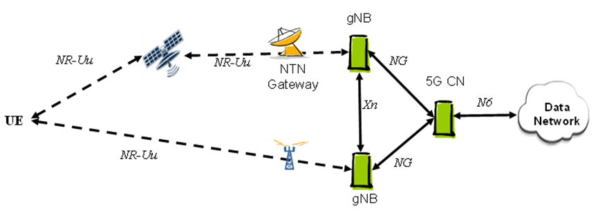 Figure 1: Multi-connectivity between NTN-based TP satellite NG-RAN and cellular NG-RAN
Either the gNB of the NTN-based NG-RAN or the gNB of the cellular NG-RAN can be selected as the master node.
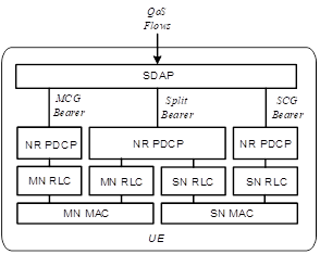 Figure 2: Radio protocol architecture of MCG, SCG, and split bearers from the UE perspective in MR-DC with 5GC
Another scenario to consider is the combination of two NTN-based TP-type NG-RANs (based on GEO or LEO, or a combination of both). This is meaningful for providing services to UEs in unserved areas. An LEO-based NTN NG-RAN with relatively low latency can be used to support delay-sensitive traffic, while a GEO-based NTN NG-RAN will provide additional bandwidth to meet target throughput requirements. As shown in the figure below.
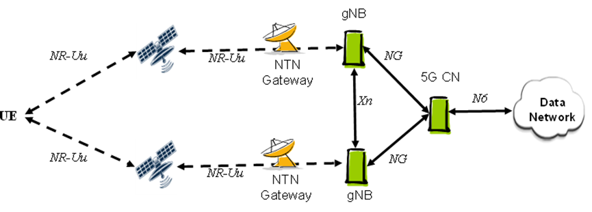 Figure 3: Multi-connectivity between two NTN-based TP-type NG-RANs
Multi-Connectivity in NTN-Based Regenerative NG-RAN (Onboard gNB-DU)
Another scenario to consider is the combination of an NTN-based regenerative NG-RAN (onboard gNB-DU) and a cellular NG-RAN. This is meaningful for providing services to UEs in underserved areas. As shown in the figure below.
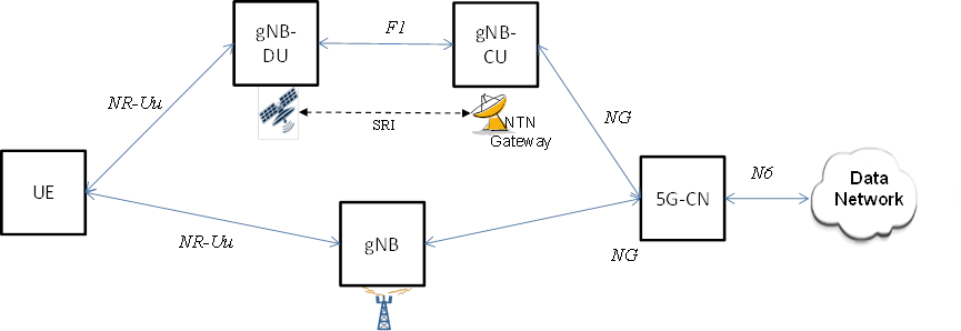 Figure 4: Multi-connectivity between NTN-based regenerative NG-RAN (gNB-DU) and cellular NG-RAN
Note that multi-connectivity may also involve two NTN-based regenerative NG-RANs (onboard gNB-DUs). (i.e., considering the onboard payload includes the DU part of the PHY layer and part of the MAC layer with high real-time requirements, while the higher-layer protocol part with lower real-time requirements, the CU, is located in ground gateway equipment.)
Multi-Connectivity in NTN-Based Regenerative NG-RAN (Onboard gNB)
The combination of two regenerative NTN-based NG-RANs (onboard gNBs), whether based on GEO or LEO, or a combination of both, with inter-satellite links to provide services to UEs in unserved areas. As shown in the figure below.
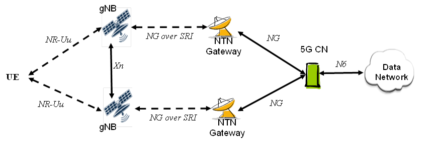 Figure 5: Multi-connectivity between two regenerative NTN-based NG-RANs (onboard gNBs) 1.3. NG-RAN Impacts
In the case of multi-connectivity in NTN-based transparent forwarding NG-RAN (i.e., gNB on the ground), all control plane and user plane interfaces toward terrestrial NG-RAN nodes terminate on the ground.
In the case of multi-connectivity involving regenerative NTN-based NG-RAN (gNB-CU on the ground, gNB-DU onboard), all control plane interfaces toward terrestrial NG-RAN nodes terminate on the ground.
For the control plane, this scenario does not pose any specific issues except that F1AP needs to accommodate the longer round-trip time of the SRI.
Regarding the user plane, the leg operating on Xn is not affected by the presence of NTN, while the leg operating on F1 (transmitted via SRI) will need to accommodate the longer round-trip time of the SRI. Overall, user plane buffering in the node carrying PDCP needs to compensate for the differences between the two interfaces. Therefore, if the terrestrial NG-RAN node participating in DC carries PDCP, that node will be affected.
In the case of multi-connectivity involving regenerative NTN-based NG-RAN with onboard gNB, establishing and maintaining the Xn interface toward the ground gNB via the feeder link will require all corresponding traffic (control plane and user plane) to be transmitted through the SRI associated with that onboard gNB. This may pose a challenge.
A prerequisite for NR-NR DC (where both the master and secondary nodes are NTN-based) is the existence of at least partial overlapping coverage areas and the establishment and operation of Xn via ISL between them. Xn connections between satellites will introduce additional latency. NR-NR DC involving satellites in close orbital positions is feasible.
The multi-connectivity process may require some adaptations to support:
Radio access technologies with significant latency
Radio access technologies that may experience variable latency within the backhaul network (e.g., Xn interfaces traversing multiple satellites located in different orbital planes)
Differential latency between the two radio access technologies involved NG-RAN should allow the necessary flexibility to select either the gNB of the NTN-based NG-RAN or the gNB of the cellular NG-RAN as the master node.
2. Service Continuity Between NTN and Terrestrial Networks
In TS 22.261 (Section 6.2.3 Service Continuity Requirements), for 5G systems with satellite access, the following requirements apply:
The 5G system should support service continuity between 5G terrestrial access networks and 5G satellite access networks owned by the same operator or by two different operators with an agreement.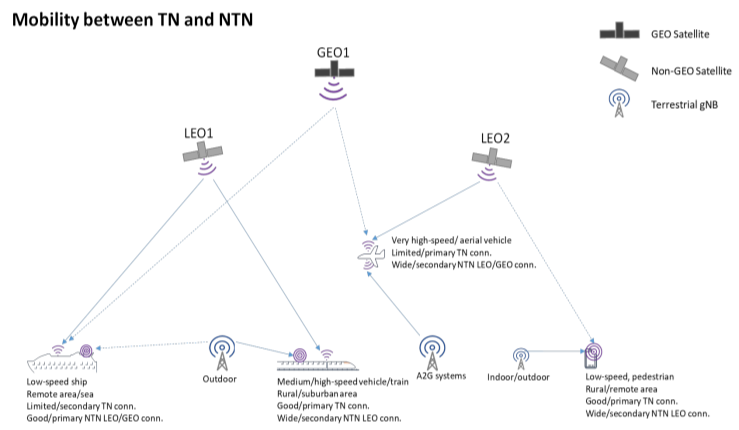 Figure 6: Typical Example of NTN-TN Interworking
NTN and TN can operate in two different frequency bands (e.g., FR1 vs. FR2) or in the same frequency band (e.g., FR1 or FR2).
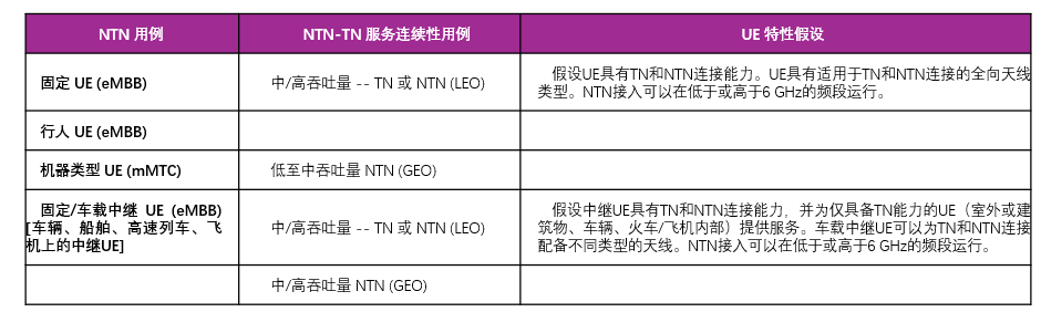
The NTN reference scenarios listed in Chapter 4.2 of 38.821 consider two types of NTN UEs: a) UEs with omnidirectional antennas, and b) UEs with directional antennas. To support NTN-TN service continuity use cases, the UE characteristic assumptions considering NTN use cases are listed in the table below:
Table 1: NTN Use Cases Mapped to TN-NTN Service Continuity Use Cases and Assumptions on Frequency Bands and UE Characteristics
2.1 Scope
The focus of the NTN-TN service continuity and mobility study should be on mechanisms that minimize specification impacts, applicable to scenarios where the UE connection changes from NTN to TN ('hand-in') and where the UE connection changes from TN to NTN ('hand-out'). Coverage mechanisms, including inter-frequency and intra-frequency service continuity and mobility mechanisms, will be considered as baseline solutions. Service continuity and mobility mechanisms from NR Release 15-16 should also be considered for the NTN-TN service continuity and mobility study.
2.2 Reference Scenarios
3GPP recommends using the following defined reference scenarios for the NTN-TN service continuity and mobility study:
Provide multi-cell TN network boundary coverage based on outdoor rural NR scenarios (e.g., Table 6.1.3-1 in TR 38.913).
An NTN LEO satellite provides multi-cell coverage with ground-moving cells (satellite NR cells modeled according to NTN assumptions, Tables 6.1.1-1 and 4 in TR38.821).
Outdoor handheld (pedestrian) UEs or VSAT (vehicular relay) UEs with TN and NTN connectivity capabilities (for NTN UEs, using Table 6.1.1-3 in TR 38.821).
2.3 Assumptions
NTN-TN service continuity and mobility mechanisms aimed at minimizing UE power consumption, such as DRX enhancement solutions, are of secondary priority.
In the baseline NTN-TN service continuity and mobility solution, studying dual connectivity mechanisms between NTN and TN is of secondary priority.
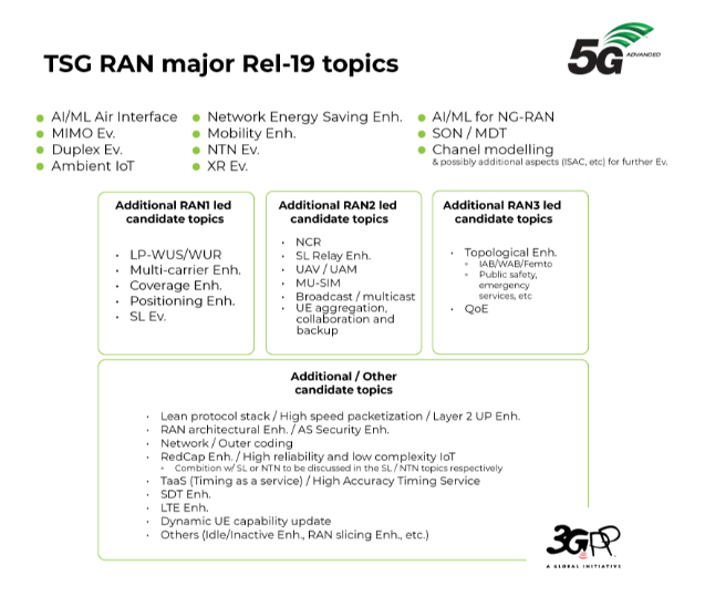 Figure 7: Main Content of 3GPP R19 RAN",
-
![]()
ByteDance, DJI, and Xiaohongshu Secure Top Three Positions Among China’s Fastest-Growing Unicorns
-
Tesla's in-car voice system in China is finally learning to 'understand human language'
-
![]()
Foreigners Are Amazed: Chinese Electric Vehicle Drive Systems Unveil Innovative 'Poses'
-
![]()
700,000 Brothers and the Future of Robots: Behind JD.com's 'Nirvana Plan'
-
![]()
Zhipu's Trillion-Dollar Valuation: A New Chapter for China's AI
-
![]()
Is Laifen, a 'Dyson Alternative' on the Rise, Now Ensnared by the 'Alternative Curse'?
-
![]()
Beyond Patents: Insta360 and DJI Compete in Retail
-
![]()
Piercing Through Industry Chaos: The Curtain Rises on Compliance for Autonomous Driving