BYD’s 8T8R Millimeter-Wave Radar Chip Delegates Perception and Computation to Central Brain
 10/10 2026
 399
399
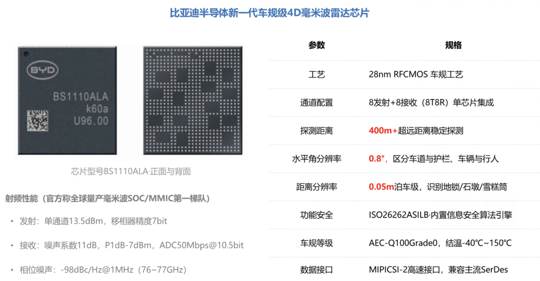
In September 2026, BYD Semiconductor announced the commencement of mass production for its latest-generation automotive-grade 4D millimeter-wave radar chip, the BS1110ALA. Built on 28nm RF CMOS technology, this single-chip solution integrates 8 transmitters and 8 receivers, delivering a detection range exceeding 400 meters, a horizontal angular resolution of 0.8 degrees, and a distance resolution of 5 centimeters. Utilizing a satellite-style architecture, the radar transmits data to the central computing platform via MIPI CSI-2 and SerDes interfaces, and has undergone joint debugging (testing and optimization) with BYD’s self-developed Xuanji A3 chip. BYD is transitioning from traditional radar modules to a collaborative design approach that integrates the RF front-end with central perception and computation.
In September 2026, BYD Semiconductor announced that its new-generation automotive-grade 4D millimeter-wave radar chip had entered mass production phase.
Based on a 28nm automotive-grade RF CMOS process, this chip integrates 8 transmit and 8 receive channels on a single die, enabling a detection range over 400 meters, a horizontal angular resolution of 0.8 degrees, and a distance resolution of 5 centimeters.
During its launch, BYD highlighted the satellite-style radar architecture. The new chip features a MIPI CSI-2 high-speed data interface, compatible with mainstream SerDes devices, facilitating radar data transmission to the central computing platform. It has completed joint debugging and adaptation with BYD’s self-developed 4nm intelligent driving chip, the Xuanji A3.
BYD is shifting from conventional millimeter-wave radar module solutions to a collaborative design approach that integrates the RF front-end with central perception and computation.
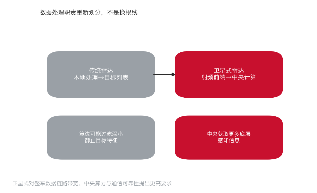
Traditional automotive radars typically perform extensive signal processing within the sensor itself, transmitting only a target list to the intelligent driving controller.
BYD’s new approach offloads more computational tasks to the central computing platform. If this architecture can strike a balance between cost, bandwidth, latency, and security, it may reshape the future hardware landscape of automotive millimeter-wave radars.
Part 1: From 3D to 4D—What Additional Capabilities Do Millimeter-Wave Radars Gain?
Millimeter-wave radars have been a staple in automotive applications for years. Early long-range radars were primarily used for adaptive cruise control and automatic emergency braking, offering the advantage of measuring the distance and relative radial velocity of vehicles ahead while maintaining detection capabilities in poor visibility conditions, such as rain or fog.
Traditional radars typically have limited angular resolution and insufficient elevation angle measurement capabilities. When encountering elevated bridges, parked trucks, or overhead traffic signs, the system must determine whether these objects obstruct the vehicle’s intended path. With sparse radar information, distinguishing the height and spatial position of objects is challenging.
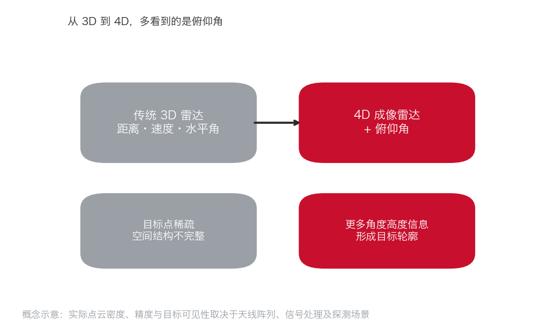
High-resolution 4D millimeter-wave radars aim to expand perception into four dimensions—distance, radial velocity, horizontal angle, and elevation angle—by employing more transmit and receive channels, virtual aperture design, and advanced signal processing.
Traditional radar target points are sparse and lack complete spatial structures; 4D imaging radars provide richer angle and height information, aiding in target contour formation. This is a conceptual illustration—actual point cloud density, accuracy, and target visibility depend on the antenna array, signal processing, and detection scenario.
4D radars enhance spatial motion information, but cameras and lidars still play distinct roles:
◎ Cameras capture texture, color, and object contours through optical imaging.
◎ Lidars obtain spatial point clouds through laser ranging.
◎ Millimeter-wave radars primarily measure target position, velocity, and partial spatial structure based on electromagnetic wave reflections.
Each sensor type has its strengths. Millimeter-wave radars excel at directly measuring radial velocity and maintaining stable detection in adverse weather conditions compared to visible light cameras.
However, they are still constrained by multipath reflections, clutter, angular ambiguity, weak reflections, and target classification capabilities. High-resolution 4D radars do not imply they can fully replace cameras or lidars.
Part 2: Why Are the Number of Transmit and Receive Channels Critical for an 8T8R Single-Chip?
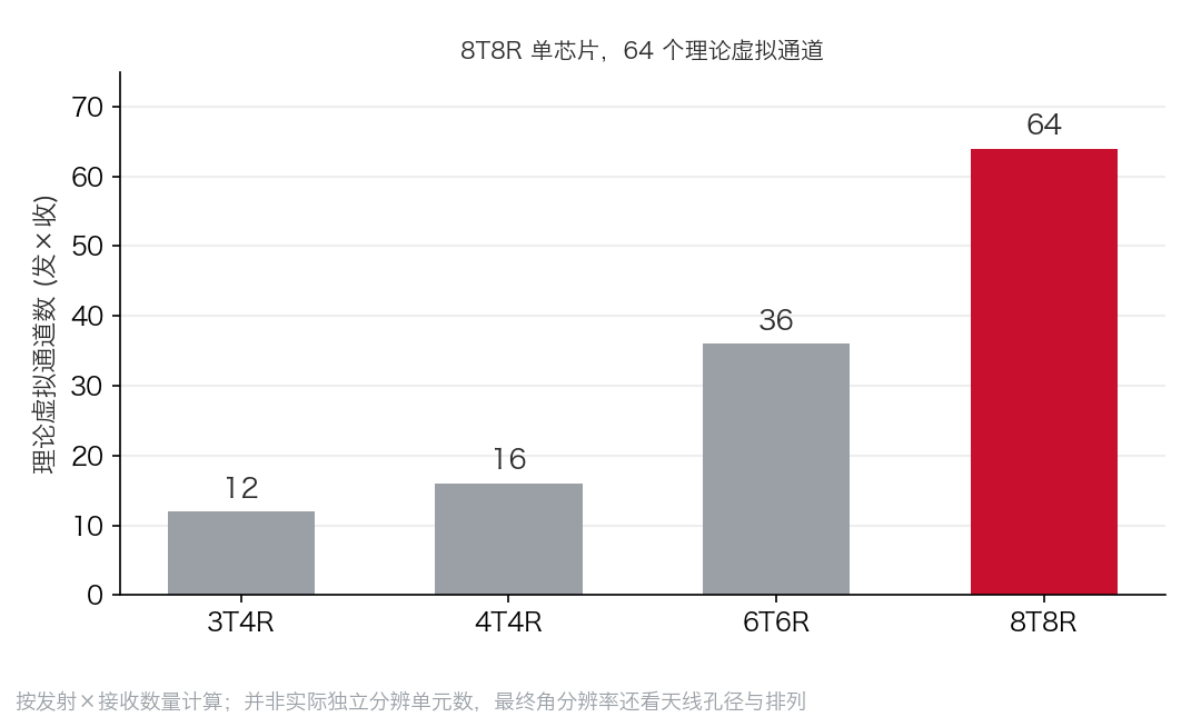
The BS1110ALA adopts an 8T8R architecture, comprising 8 transmit and 8 receive channels.
For FMCW millimeter-wave radars, the transmit antenna emits a frequency-modulated continuous wave, and the receive antenna captures the target’s reflected signal. By analyzing the frequency difference, phase relationship, and multiple measurement results between the transmitted and received signals, the distance, velocity, and angle are calculated.
In MIMO radars, multiple transmit and receive channels can form a virtual array through specific orthogonal transmit signal methods and antenna arrangements. Ideally, 8 transmitters and 8 receivers can create 64 virtual transmit-receive combinations.
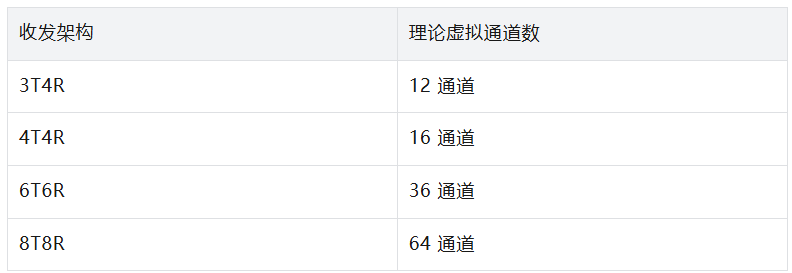
Integrating 8T8R on a single chip offers two primary advantages: it reduces the design complexity associated with using multiple transmit-receive chips to achieve more RF channels.
When multiple RF chips form a radar system, considerations such as inter-chip clock synchronization, phase consistency, RF connections, power supply, and calibration increase system design and manufacturing complexity.
Increasing the number of transmit-receive channels provides greater flexibility for antenna aperture design and beamforming.
The final angular resolution of 64 virtual channels depends on the actual antenna aperture, arrangement, wavelength, signal-to-noise ratio, signal processing methods, and available scanning time.
If virtual channels are too densely packed without increasing the effective array aperture, resolution improvements may be limited. Additionally, more transmit-receive channels increase power consumption, data sampling volume, and calibration complexity.
BYD announced three core detection metrics, corresponding to long-range detection, angular differentiation, and distance resolution.

The maximum detection range of millimeter-wave radars depends on transmit power, antenna gain, receiver sensitivity, signal processing gain, and the target’s radar cross-section. The effective detection range of the same radar may vary significantly for large trucks, ordinary passenger vehicles, motorcycles, and pedestrians.
In high-speed scenarios, a longer detection range helps acquire vehicle motion information in advance. At a speed of 120 kilometers per hour, a vehicle travels approximately 33.3 meters per second, so 400 meters corresponds to about 12 seconds of travel time.
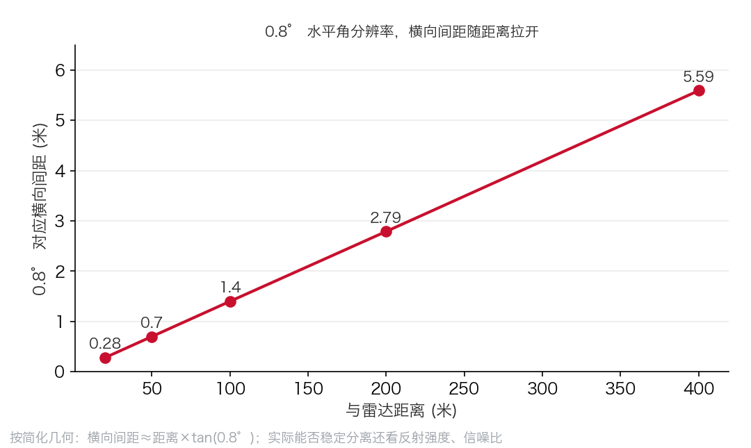
Angular resolution describes the radar’s ability to distinguish targets at similar angles. For targets at the same angular interval, the farther the distance, the larger the lateral distance in space.
Based on simplified geometric relationships, at 20 meters, 0.8 degrees corresponds to a lateral spacing of about 0.28 meters; at 50 meters, about 0.70 meters; at 100 meters, about 1.40 meters; at 200 meters, about 2.79 meters; and at 400 meters, about 5.59 meters.
The theoretical distance resolution of FMCW radars is primarily determined by the effective frequency modulation bandwidth, approximately equal to the speed of light divided by twice the effective bandwidth.
To achieve a theoretical distance resolution of 5 centimeters, an effective bandwidth of about 3 GHz is required, which is technically feasible through broadband signal design within the 77 GHz to 81 GHz automotive radar frequency band.
Part 3: How Does This Chip Compare in Terms of RF Specifications?
Rather than focusing solely on the 400-meter detection range, it is more appropriate to evaluate the chip’s RF performance from a semiconductor perspective. BYD disclosed parameters including 13.5 dBm single-channel transmit power, 7-bit phase shifters, an 11 dB noise figure, 10.5-bit ADC effective resolution, and phase-locked loop (PLL) phase noise.
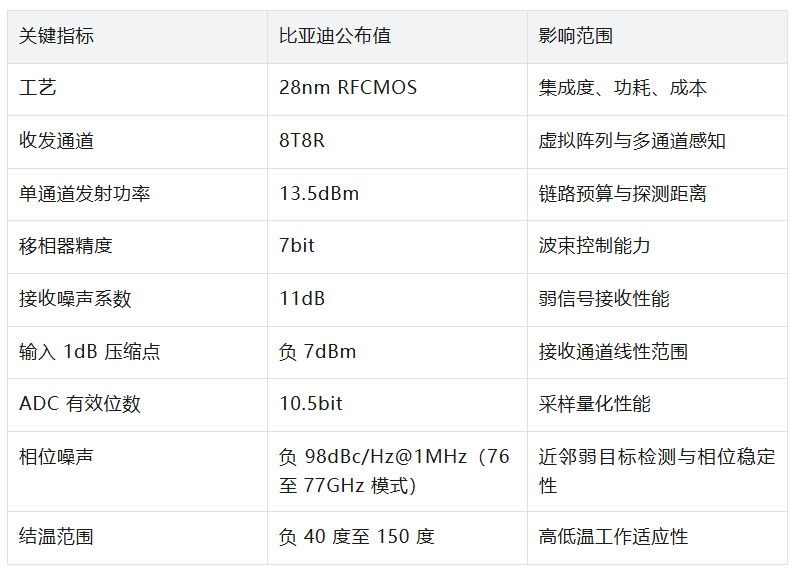
From a technical standpoint, transmit power, noise figure, and phase noise collectively determine the fundamental capabilities of the radar’s RF link.
A single-channel transmit power of 13.5 dBm corresponds to approximately 22.4 milliwatts of RF output power. This cannot be directly equated to the equivalent isotropically radiated power (EIRP) of the entire radar module, as antenna gain, channel combination methods, and regulatory restrictions also influence the final output.
An 11 dB noise figure describes the degradation of the signal-to-noise ratio (SNR) in the receive link. Under the same bandwidth, gain, and other conditions, a lower noise figure generally favors weak target detection.
Phase noise is equally important. Automotive millimeter-wave radars often process both strong and weak reflecting targets simultaneously. For example, a large truck with strong radar reflections may be nearby, while smaller targets with weak reflections are also present.
When the PLL phase noise is high, spectral leakage from strong targets may interfere with the identification of nearby weak targets. Low phase noise improves target detection conditions in complex scenarios.
Automotive millimeter-wave radars typically adopt a relatively independent sensor design.
A radar module internally contains an RF chip, signal processing unit, memory, power management, and communication interface. After receiving a reflected signal, the radar first completes range FFT, Doppler FFT, angle estimation, target detection, and tracking locally before transmitting a target list to the intelligent driving domain controller. This architecture offers advantages such as maturity and low communication bandwidth requirements but also has limitations.
Internal radar algorithms may filter out weak, stationary, or uncertain targets.
The processed target list is more compact but may lose some original reflection characteristics. As intelligent driving systems increasingly rely on unified environment modeling, the central computing platform desires more low-level perception information, leading to the development of satellite-style radars.
In BYD’s new solution, the radar front-end transmits data to the central computing platform via MIPI CSI-2 interfaces and SerDes links, with the central platform handling more radar signal processing and perception fusion tasks. The key is the reallocation of data processing responsibilities, not simply replacing a CAN bus with a high-speed transmission line.
Take the 8T8R chip as an example: if 8 receive channels simultaneously sample at 50 MS/s and each sample is transmitted at 16 bits, the uncompressed single-component data volume can theoretically reach 6.4 Gbps. If both I/Q components are transmitted, the data rate may further increase.
Actual systems employ various sampling timing, data bit widths, channel multiplexing, and front-end processing schemes, placing significantly higher demands on the vehicle’s data links. MIPI CSI-2 and SerDes provide high-speed data transmission means, but the central intelligent driving chip must have sufficient memory bandwidth and signal processing capabilities to handle this data.
Such architectures may reduce local processor configurations and duplicate computations, allowing multiple radars to run unified algorithms, but they increase central computing load and communication reliability requirements.
The self-developed Xuanji A3 automotive-grade 4nm intelligent driving chip was released and entered mass production in May. The collaborative operation of three chips delivers a total computing power exceeding 2100 TOPS, reduces power consumption per unit of computing power by 20% compared to similar solutions, and supports computing demands for L3 and L4 applications.
BYD’s Xuanji Architecture 2.0 promotes centralized computing and intelligent assisted driving system upgrades, providing the hardware foundation for satellite-style millimeter-wave radars.
After radar data is centralized to the central computing platform, the central SoC must process inputs from cameras, lidars, and other sensors while also handling a significant portion of radar signal processing. Traditional radar processing involves extensive FFT, matrix computations, beamforming, constant false alarm rate (CFAR) detection, and subsequent target estimation.
Part 4: How Does BYD’s Approach Compare to NXP and Texas Instruments?
In the global automotive millimeter-wave radar chip market, international companies such as NXP, Texas Instruments, and Infineon have long established the primary technical and customer ecosystems.
◎ NXP offers both highly integrated radar SoCs and discrete RF transceivers paired with radar processors. For example, the S32R47 targets high-resolution imaging radars, features dedicated radar signal processing acceleration resources, and provides high-speed interfaces such as MIPI CSI-2 and Ethernet.
◎ Texas Instruments’ AWR2944P is a 4T4R automotive-grade millimeter-wave radar SoC that integrates an Arm processor, C66x DSP, and radar hardware accelerators, emphasizing compact single-chip radar system capabilities.
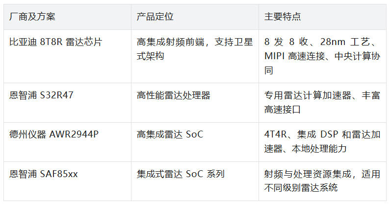
The competition within the millimeter-wave radar sector is evolving along two distinct paths:
◎ One strategy focuses on achieving deeper integration of radio frequency (RF), computing, and control functionalities into local system-on-chips (SoCs). This approach aims to streamline the system by minimizing the number of components and external connections, thereby delivering sophisticated, autonomous intelligent radar modules.
◎ The alternative strategy involves boosting the data output capabilities of the radar's RF front-end, thereby offloading more computational tasks to the central processing platform.
Neither of these technical approaches holds absolute superiority over the other.
◎ For applications such as low-cost corner radars, blind spot monitoring, and basic assisted driving systems, locally integrated SoCs continue to offer significant advantages due to their cost-effectiveness and simplicity.
◎ Conversely, for advanced assisted driving systems equipped with high-performance central processors, multiple cameras, and radars, the satellite architecture opens up new avenues for system optimization and performance enhancement.
BYD is currently placing a strong emphasis on the development of 8T8R single-chip solutions and satellite-based data transmission, with the aim of complementing its centralized intelligent driving architecture.
Globally, the adoption of 8T8R technology and central processing is not exclusive to BYD; other manufacturers are also making strategic moves in this area. Therefore, BYD's competitive standing should be assessed based on a comprehensive evaluation of transceiver performance, overall system cost, power consumption, effective detection capabilities, and the scale of mass production.
Summary
BYD is making strides in the realm of highly integrated RF chip design and is also exploring the potential of shifting perceptual computing tasks from standalone sensors to central computing platforms. It remains a company worth watching closely in this dynamic sector.
-
![]()
The Rise of AI Travel in a New Era | WeTides
-
![]()
Huawei Mate 90 Pro Max Review: Stellar Imaging, HarmonyOS Ecosystem Excels
-
![]()
The Enigma of the $1.2 Billion Loan and the Flagship Price Surge: Why is OPPO Raising Funds Amid an Industry Slump?
-
![]()
A Puzzle Behind $1.2 Billion Loan and Flagship Price Hike: What Is OPPO Preparing for During Industry Adjustment Period?
-
![]()
BYD’s 8T8R Millimeter-Wave Radar Chip Delegates Perception and Computation to Central Brain
-
![]()
Did the 'Golden September' Phenomenon Fail to Materialize? Auto Market Experiences Sales Dip Amidst High Base, Yet 'Not Cold'
-
![]()
Circular Aperture, Square Aperture, Double Slit: Three Optical Fingerprints of Diffraction and Interference
-
![]()
Post-90s Tsinghua PhD Raises 300 Million Yuan for AI Video Startup