[5G PHY Series] Physical Layer Signals and Channels
![]() 12/09 2024
12/09 2024
![]() 666
666
1. Introduction
Since the release of the first international standard R15 for 5G in 2018, it has been five or six years, and the penetration rate of 5G users in China has reached 60%. However, we also notice that the development of 5G faces challenges such as high construction costs and insufficient market demand, limiting the high-speed and high-bandwidth application scenarios, which has given rise to versions like Lightweight 5G.
In recent years, we have also observed that low-orbit satellite communications, represented by Starlink, are becoming a hot topic, providing network coverage services for remote areas and underdeveloped regions with poor terrestrial networks.
5G-NTN technology is also emerging as one of the low-orbit satellite communication systems, and several domestic manufacturers are currently conducting in-orbit validation tests. From a technical perspective, it is expected that various satellite communication systems will adopt a fusion development strategy that leverages each other's strengths, effectively complementing terrestrial networks to truly realize the "Internet of Everything".
The design of the physical layer is the core part of the entire 5G communication system. The '5G PHY' series will successively introduce content related to the 5G physical layer, including the concepts, functions, processing flows of various channels, and MATLAB implementations. Table 1 briefly introduces the content covered by the 5G PHY protocol specification.
Table 1 5G PHY Protocol Specification

This article will introduce the standard specifications and technical implementation processes related to physical channels and signals in the 5G physical layer.
2. 5G Physical Signals 2.1 NR Downlink Physical Signals
Functionally, NR downlink physical signals include:
Channel State Information Reference Signal (CSI-RS): Used for downlink channel measurement, beam management, RRM/RLM measurement, and fine time-frequency tracking.
Demodulation Reference Signal (DM-RS): Used for downlink data demodulation, time-frequency synchronization, etc.
Tracking Reference Signal (TRS): Used for downlink time-frequency error estimation and tracking.
Phase Noise Tracking Reference Signal (PT-RS): Used for downlink phase noise tracking and compensation (in high-speed mobile scenarios).
Downlink Synchronization Signals: Including Primary Synchronization Signal (PSS) and Secondary Synchronization Signal (SSS), used for time-frequency synchronization and cell search.
2.2 NR Uplink Physical Signals
NR uplink physical signals include:
Sounding Reference Signal (SRS): Used for uplink channel measurement, time-frequency synchronization, beam management, etc.
Demodulation Reference Signal (DM-RS): Used for uplink data demodulation, time-frequency synchronization, etc.
Phase Noise Tracking Reference Signal (PT-RS): Used for uplink phase noise tracking and compensation (in high-speed mobile scenarios).
3. Physical Channels
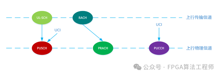
Physical channels correspond to a specific set of time/frequency resources used to carry transmission channels mapped from higher layers. Each transmission channel is mapped to a physical channel, and the specific mapping relationships are shown in Figures 1 and 2. From the figures, we can see that some physical channels do not carry transmission channels and are referred to as control channels.

Figure 1 Downlink Transmission Channel Mapping 3.1 Physical Downlink Channels
The Physical Downlink Control Channel (PDCCH) carries Downlink Control Information (DCI), providing necessary information for the UE to receive downlink and transmit uplink, such as resource allocation information. PDCCH is used to transmit DCI, primarily the scheduling information required for the UE to receive PDSCH and transmit the Physical Uplink Shared Channel (PUSCH). It can also transmit Slot Format Indicator (SFI) and Preemption Indication (PI), among other things. The antenna port for PDCCH is 2000.
The Physical Downlink Shared Channel (PDSCH) is primarily used for the transmission of downlink unicast data and can also be used for paging messages and system messages. PDSCH is transmitted on antenna ports 1000 to 1011.
The Physical Broadcast Channel (PBCH) carries part of the minimum system information required for UE access to the network. The antenna port for PBCH is 4000.
3.2 Physical Uplink Channels

Figure 2 Uplink Transmission Channel Mapping
The Physical Uplink Control Channel (PUCCH) carries Uplink Control Information (UCI), used to report the status of the UE to the base station, such as HARQ reception status and channel state information. PUCCH carries UCI, feeds back HARQ-ACK information to indicate whether the downlink transport block was correctly received, reports channel state information, and requests uplink resources when uplink data arrives. The antenna port for PUCCH is 2000.
The Physical Uplink Shared Channel (PUSCH) corresponds to the uplink physical channel of PDSCH and is used to transmit uplink service data and can also carry UCI. PUSCH is transmitted on antenna ports 1000 to 1003.
The Physical Random Access Channel (PRACH) is used for the random access process, with an antenna port of 4000.


