Is It Possible to Break a Car's Brake Pedal by Stepping on It Too Hard? Can a Driver Fully Depress the Brakes?
 10/12 2026
 479
479
In a car, there are two pedals that are used daily: the accelerator and the brake. Positioned close together and resembling each other in appearance, both pedals are operated with the right foot—one for speeding up and the other for slowing down. Although they share some similarities, their functions, force transmission mechanisms, and the consequences of failure differ significantly.
Produced by Zhineng Technology
On October 8th, Dongchedi conducted an emergency braking test from 100 km/h to 0 km/h, during which the brake pedal brackets of three Zunjie V800 vehicles successively fractured.
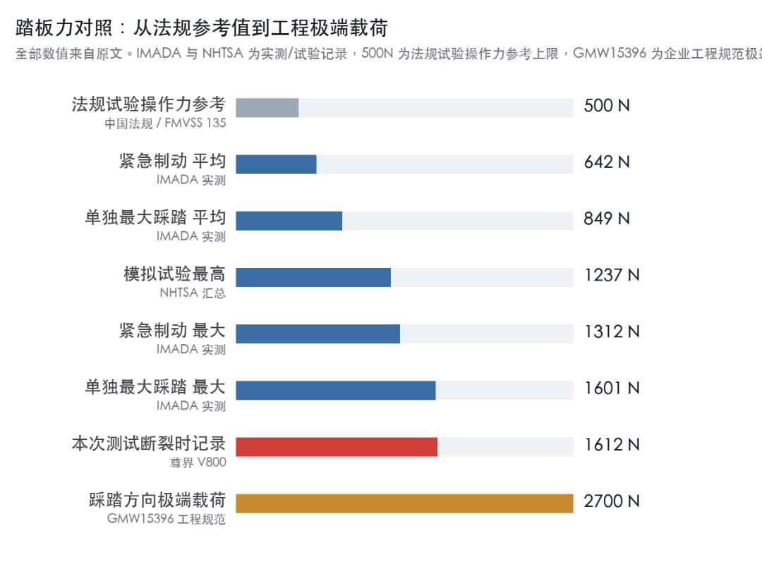
The fractures occurred during the third, fourth, and second full-force braking attempts for the three vehicles, respectively, with similar failure locations. The maximum pedal force recorded in the third vehicle was 1612N.

Zunjie subsequently issued a statement, claiming that the brake system was developed and validated according to requirements that exceed national and industry standards. This incident occurred under non-standard extreme testing conditions, and further optimization of component design will be conducted, with free upgrade options provided to delivered users.
On one hand, this is seen as a safety risk during emergency braking; on the other hand, it is emphasized that the testing conditions exceeded normal usage.
In the ensuing debate, two questions stand out as the most worthy of discussion:
◎ First, how robust should a brake pedal be? Can an average person exerting full force break the pedal?
◎ Second, during a frontal collision, should the pedal be designed to collapse or detach to avoid injuring the driver's ankle and lower leg?
Should the same component be made sturdy, or should it be allowed to fracture under certain conditions?
To answer these questions, one must first understand the structures of the accelerator and brake pedals, as well as how engineers address forces in different directions and scenarios.
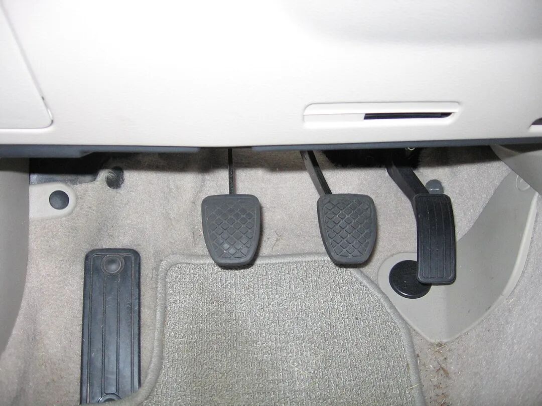
In a traditional passenger vehicle's footwell area, from left to right, are generally the clutch (only present in fuel vehicles with manual transmissions), brake, and accelerator pedals. While the three pedals appear similar, their internal structures, force transmission methods, and failure consequences differ significantly.
01 Accelerator and Brake Pedals: Similar Appearance, Vastly Different Design Requirements
Accelerator Pedal: Driver's Power Demand
Early fuel vehicles connected the accelerator to the throttle via a cable. Stepping on the pedal pulled the cable, opening the throttle and increasing engine air and fuel intake.
Modern vehicles generally use electronic accelerator pedals. When the pedal is depressed, the pedal arm rotates around a pivot, and a position sensor measures the travel, sending acceleration demands to the vehicle controller. The controller then determines the torque output of the engine or motor based on vehicle speed, drive state, and safety strategies.
Common electronic accelerator pedals typically feature dual-channel position detection, return springs, mechanical stops, and fault diagnostics. US FMVSS 124 regulations govern the return to idle when the accelerator is released and the safety behavior when the control mechanism is disconnected.
A key point: The accelerator pedal governs power requests. The pedal itself usually does not directly transmit the output torque of the motor or engine.
If the electronic accelerator pedal arm fractures, the normal fault protection direction is to prevent the vehicle from receiving acceleration requests and to limit power, avoiding uncontrolled acceleration. The ability to correctly identify faults depends on sensor signals and control strategies.
The design focus of the accelerator pedal lies in pedal feel, accuracy of position detection, reliable return, sensor redundancy, power control after faults, and durability under repeated depression. The pedal depression force is usually small, with tens of newtons sufficient for most travel, and drivers have no reason to apply excessive force.
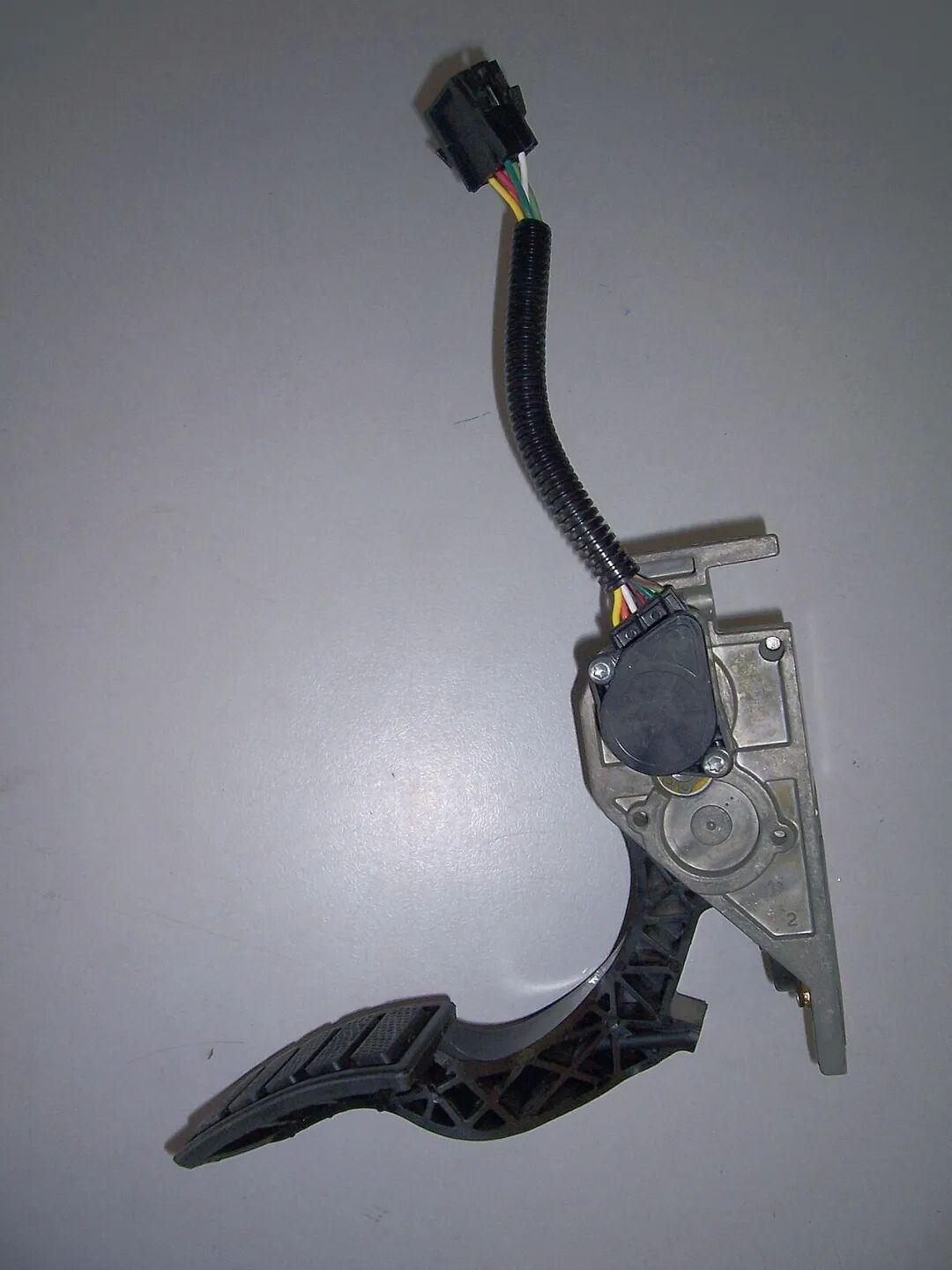
An electronic accelerator pedal assembly primarily consists of a metal mounting plate, pedal arm, position sensor module, and a bundle of wires at the top. While it contains many mechanical components, it transmits electrical signals, not power torque.
Brake Pedal: Driver Must Reliably Decelerate the Vehicle
The operation of traditional brake pedals is more complex. When depressed, force is transmitted through the pedal arm, pivot, pushrod, to the brake booster and master cylinder. The system builds hydraulic pressure, which drives the wheel brakes via brake lines.
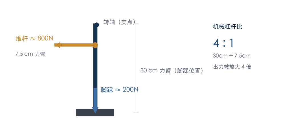
Assuming an effective force arm from the pedal pivot to the foot position of 30 cm and from the pivot to the pushrod connection of 7.5 cm, neglecting friction and angular changes, the mechanical leverage ratio is 4:1.
If the driver applies 200N, theoretically, the pushrod end can generate approximately 800N, with additional amplification from the brake booster. This is a simplified model. The actual pushrod force is also influenced by pedal angle, linkage geometry, stop structure, and booster state.
The brake pedal must reliably transmit the driver's force while withstanding complex loads between the pivot, pushrod, and bracket, especially during emergency braking.
Drivers often quickly and forcefully depress the pedal, and when the pedal travel approaches the mechanical stop, the depression force is also transmitted to the vehicle body via the stop mechanism and mounting bracket.
With electro-hydraulic brakes, the force transmission method changes. Bosch's integrated electro-hydraulic brake system uses sensors to identify the driver's braking demand, with the motor building pressure and pedal feel provided by a simulation mechanism.
Some architectures retain a hydraulic-mechanical backup channel, while fully decoupled brake-by-wire systems rely on redundant sensors, electronic control, and brake actuators.
Regardless of the solution, the pedal and bracket must first ensure that the driver can reliably input braking demands.
If fracture renders the pedal travel imperceptible or the mechanical pushrod inoperative, even if the calipers, brake discs, and hydraulic controller are functioning, the driver may be unable to brake normally using the foot pedal.
When compared side by side, the differences become clear.
How significant is 1612N? Can a normal person generate that much force?
We are accustomed to measuring weight in kilograms but rarely discuss force in newtons. 1612N is approximately the gravitational force acting on a 164 kg object on the Earth's surface.
It sounds impressive. Some may ask: How can a person weighing seventy to eighty kilograms exert a force more than twice their body weight?
Because braking is not equivalent to standing on a weighing scale. Seated in the driver's seat, with the back against the seatback, the pelvis and body supported by the seat, and the thighs and calves working together, the reaction force from the seatback allows the foot to output a force exceeding body weight. During emergency braking, the driver's actions may also be quite vigorous.
Measurements of ordinary people's braking forces have been conducted.
IMADA, a Japanese force measurement instrument company, tested over 50 participants aged 30 to 70-plus. Simulating normal driving emergency braking, the maximum recorded force was 1312N, with an average of 642N. In separate maximum depression tests, the maximum was 1601N, with an average of 849N.
An NHTSA research report summarizing driving simulation experiments also recorded a maximum pedal force of 1237N.
Drivers can indeed generate forces exceeding 1000N. A force of 1612N represents a very high pedal force, with the maximum achievable force depending on depression posture, seat position, physical strength, depression speed, and pedal position.
If 1612N is possible, why do regulations often specify 500N?
Chinese braking regulations and US FMVSS 135 include requirements for brake pedal operating force. In some braking performance tests, 500N is the pedal force limit used by drivers to achieve specified braking performance.
A car door normally requires only a small force to close, but the door hinges obviously cannot be designed based solely on daily closing forces. One must consider scenarios such as forceful slamming, doors being blown by wind, or the vehicle body twisting during bumps.
The same logic applies to brake pedals. Under normal conditions, 200N to 300N can achieve strong braking; however, in sudden dangerous situations, drivers may still press with full body force on the pedal. Designers must incorporate such scenarios into structural safety analyses.
The industry also has specialized pedal bench standards. QC/T 788-2018 "Automotive Pedal Device Performance Requirements and Bench Test Methods" specifies performance and testing methods for brake and clutch pedals, with longitudinal loading tests involving 1500N-class loads, verified according to specified loading positions, holding times, and cycle counts.
Note that this standard directly applies to mechanically hinged metal brake and clutch pedals, with other types of pedals able to refer to its implementation.
Vehicle manufacturers often set even stricter internal specifications. General Motors' 2007 GMW15396 specification imposes an extreme load of 2700N in the pedal depression direction for brake pedals, with additional requirements for lateral loads. Porsche's MSB platform once used a 3000N fracture load as one of its design verification indicators.
Why should pedals collapse during collisions?
This question is the most prone to misunderstandings. In severe frontal collisions, pedals should be designed to fracture to avoid injuring the driver's ankle.
This assertion has a basis in automotive engineering. Pedal collapse design during collisions and strength design for normal driver pedaling represent two different operating conditions.
◎ Why are ankles vulnerable in frontal collisions?
Imagine a driver traveling at high speed when an obstacle suddenly appears ahead. The driver quickly depresses the brake, firmly pressing the foot on the pedal. A severe frontal collision then occurs.
The vehicle's front end absorbs the impact, potentially deforming the engine compartment and firewall. The brake pedal bracket, mounted near the firewall, may also move toward the driver.
At this point, the driver's leg may still be in the braking posture. If the pedal assembly is very sturdy and continues to intrude toward the driver, it may impose significant loads on the foot, lower leg, and ankle.
Such loads can cause excessive ankle dorsiflexion, torsion, or even lower limb fractures. Therefore, engineers must consider preventing pedal rearward intrusion during collisions.

Crash test dummy. In collision safety, loads on the ankle and lower leg are quantified by sensors on the dummy. The original intent of pedal collapse design is to control pedal intrusion toward the driver during collisions, reducing lower limb injuries.
◎ How do collapsible pedals protect drivers?
One approach is to incorporate dedicated collision release mechanisms into the pedal assembly.
During normal driving, the pedal arm, pivot, and bracket remain firmly connected, allowing normal brake force transmission. In the event of a severe frontal collision, significant relative displacement occurs between the firewall and instrument panel crossmember, triggering specific mechanisms that allow the pedal pivot to disengage or altering the pedal's motion direction via linkages.
This allows the pedal to move forward or reduces the reaction force on the driver's foot.
Patents for collapsible pedal mechanisms have existed since the 2000s. In 2026, Tata Motors published an engineering study on collapsible brake pedals, emphasizing the reduction of lower limb injury risk via collision release linkages without compromising daily braking performance.
The European New Car Assessment Programme (Euro NCAP) also explicitly focuses on pedal rearward and upward movement and sticking after collisions. If a pedal is designed to completely detach from its mounting points during a collision and indeed releases without significant motion resistance during testing, its displacement evaluation may adopt different handling methods.
This indicates that some pedals are indeed allowed to detach during collisions.
Collision release mechanisms are triggered by predetermined collision motions or load paths. The loads from driver pedaling and those caused by firewall intrusion may act in completely different directions and locations on the bracket.
The ideal design maintains sufficient strength during normal use and emergency braking while relying on dedicated mechanisms to release during severe collisions meeting design conditions.
If simply applying force to the pedal causes the bracket to lose load-bearing capacity, further verification is needed to determine whether this is an intended design and whether brake safety can still be ensured after pedal fracture.
Not all forms of pedal fracture can be explained as collapse design to protect the ankle.
02 Why Were Brake Pedals Traditionally Metal, and Why Are Plastics Increasingly Used Now?
Many people's first reaction upon seeing plastic brake pedals is that automakers, seeking cost savings, replaced sturdy steel pedals with plastic ones.
The reality is more complex.
Metal Pedals Were Used for Many Years
In the realm of traditional brake pedal assemblies, pedal arms and brackets were predominantly crafted from stamped steel plates, steel tubes, and welded steel structures. Some high-end models and specialized applications opted for aluminum alloys.
The merits of metal are evident. Steel boasts a high elastic modulus, excellent stiffness, and a relatively robust capacity for plastic deformation. Its material properties and welding manufacturing processes are well-established. For brake pedals subjected to bending moments, torques, and repeated loads, steel structures offer a relatively reliable design and verification framework.
However, metal pedals also come with drawbacks. The primary concern is weight: although the combined weight of the pedal arm, bracket, pins, and fasteners per vehicle is not substantial, engineers are always on the lookout for opportunities to reduce weight. The manufacturing process is another challenge: stamping, bending, welding, corrosion protection, and assembly involve multiple steps. Complex reinforcing ribs and mounting structures may also increase the number of parts.
Consequently, transitioning from metal to composite materials has long been a strategy in automotive lightweighting.
Porsche Leads the Way in Composite Brake Pedals
Porsche serves as a prime example.
In a 2018 technical article, Porsche introduced brake pedals made from thermoplastic glass fiber composite materials, highlighting their high strength, lightweight construction, and long-term stability.
By 2019, Lanxess publicly unveiled its Tepex continuous fiber-reinforced thermoplastic composites, which were used in the brake pedals of Porsche models such as the 918 Spyder, Macan, and Panamera.
In 2020, Lanxess and BOGE jointly revealed a fully plastic brake pedal solution tailored for electric sports cars.
This structure utilizes a PA6-based continuous glass fiber composite material, locally reinforced with unidirectional fiber tapes, and overmolded with PA66 injection molding. The supplier claims a weight reduction of approximately 50% compared to similar steel pedals.
The forces acting on the brake pedal follow a clear transmission path. By aligning glass fibers along the primary force direction, the tensile and bending resistance of the fibers can be fully exploited.
Lanxess employs a layering technique with fibers at different angles, supplemented by localized reinforcement tapes, to enhance bending and torsional stiffness. This approach differs significantly from ordinary injection-molded plastic parts.

The brake pedal of the Porsche 918 Spyder incorporates Lanxess's continuous fiber-reinforced thermoplastic composite material (Tepex). Hypercars, being highly sensitive to weight reduction, were early adopters of composite materials for load-bearing components like brake pedals. Image source: Wikimedia Commons (CC licensed).
Timeline of Composite Brake Pedals:
◎ 2018: Porsche published a technical article introducing thermoplastic glass fiber composite brake pedals, emphasizing their high strength, lightweight design, and long-term stability.
◎ 2019: Lanxess introduced Tepex continuous fiber-reinforced thermoplastic composite material, which was applied in the brake pedals of models such as the Porsche 918 Spyder, Macan, and Panamera.
◎ 2020: Lanxess and BOGE announced a fully plastic brake pedal solution for electric sports cars, with suppliers reporting a weight reduction of approximately 50% (compared to similar steel pedals).
Engineering plastics and fiber-reinforced composite materials have emerged as crucial choices for automotive structural components.

Even with the same PA66 material, variations in glass fiber content, fiber length, and molding processes can lead to significant differences in mechanical properties. For the same material, differences in rib design, wall thickness, and gate layout can also result in varying structural load-bearing capacities.
For instance, in a brake pedal arm primarily subjected to bending forces, optimal reinforcement is achieved when the glass fiber direction aligns with the principal tensile stress direction. However, weak points may emerge in critical areas due to obvious weld lines, unfavorable fiber orientation, or abrupt local wall thickness changes.
Plastic parts require special attention to long-term creep under load, as well as the impact of temperature, humidity, and aging on strength, stiffness, and toughness. Therefore, assessing the reliability of a plastic brake pedal involves evaluating the material grade, part geometry, molding process, and actual loading conditions.
Metal pedals can be poorly designed, while composite pedals can be exceptionally robust. The final judgment depends on the engineering validation results of the entire assembly.
Regarding the bracket material involved in this controversy, the manufacturer's provided material grade, structural drawings, and third-party testing results should form the basis for evaluation, rather than relying solely on fracture photographs to determine material or failure causes.
How is Pedal Strength Designed? The Key Lies in the Bracket, Pivot, and Load Path.
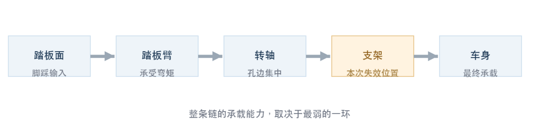
What drivers see are the pedal surface and a segment of the pedal arm beneath their feet. The brake pedal assembly also includes a pivot, bushings, springs, pushrod connection points, mounting base, fasteners, and a bracket structure connecting to the vehicle body. When the driver presses the pedal downward, all these components are subjected to forces.
A robust pedal arm paired with an inadequately stiff mounting bracket may result in significant bracket deformation under load. A sturdy bracket, but with insufficient material around the pivot hole, may concentrate loads at the hole edge.
Even if both the pivot and bracket are sound, local stress concentrations around plastic fastener holes or unreasonable fastener preload and connection designs can still lead to failure.
The load-bearing capacity of a brake pedal assembly depends on the strength of each component along the entire load path.
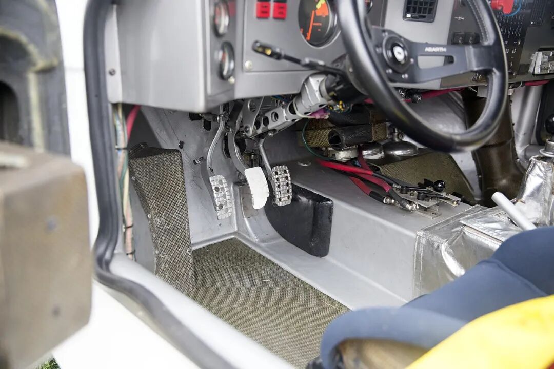
Racing pedal assembly. Lifting the floor mat reveals the complete mechanism: pedal arm, pivot, bracket, and linkages, all mounted on a single base.
◎ First Requirement: No Significant Permanent Deformation Under Normal Use
Elastic deformation is acceptable during pedal operation. However, if the pedal position changes, the pedal feel alters noticeably, or pivot play increases significantly after a heavy brake application, it suggests permanent deformation or damage to the components.
Structural design must consider not only maximum stress but also control pedal surface displacement, pivot clearance, pushrod deflection angles, and relative deformation between the bracket and vehicle body. This is especially critical for plastic parts. Meeting initial strength requirements does not guarantee long-term dimensional stability.
◎ Second Requirement: Account for Pedal Forces in All Directions
Drivers rarely apply brake force precisely at the pedal center. Foot placement may vary—sometimes with the toe, sometimes at the edge—and emergency braking may introduce significant lateral forces.
For example, General Motors' 2007 GMW15396 engineering specification outlines requirements for brake pedal force direction and lateral loads, specifying extreme loads of 2700N in the pedaling direction and 440N laterally.
Design must account for variations in load direction. A force applied at the pedal center primarily transmits along the normal operating direction.
The same force applied at the pedal's outermost edge generates bending moments and may introduce torsional forces, causing one side of the bracket to experience additional tension or shear. For plastic brackets, stress concentrations are particularly critical at bolt holes, pivot holes, rib intersections, and abrupt wall thickness changes.
This is why knowing only the peak pedal force is insufficient to fully assess the component's safety margin.
◎ Third Requirement: Withstand High Forces and Hundreds of Thousands of Repetitive Cycles
Automotive design lifespans span years and hundreds of thousands of kilometers. Drivers repeatedly apply the brakes daily, subjecting the pedal to extensive cyclic loading. Engineers must verify that components do not develop cracks, loosening, wear, or fatigue failure after prolonged repetitive loading.
Environmental factors must also be considered. Low temperatures in cold regions can alter the impact behavior of polymeric materials, while summer heat can significantly raise interior temperatures after sun exposure. For hygroscopic nylon materials, humidity can similarly affect dimensional and mechanical properties.
Therefore, a qualified pedal assembly typically undergoes various validations covering static strength, stiffness, repetitive loading endurance, vibration, temperature, humidity, and extreme loads.
More stringent companies also conduct ultimate load tests on samples subjected to environmental aging and durability testing to evaluate the material's residual load-bearing capacity after long-term use.
◎ Fourth Requirement: Ultimately Align with Crash Safety Requirements
This brings us back to crash collapse.
Under normal braking, the pedal must maintain structural integrity. During severe frontal collisions, pedal intrusion into the driver's foot space and the resulting loads must be controlled.
If a dedicated crash release mechanism is used, two aspects must be verified simultaneously: it must not trigger unexpectedly during normal use or foreseeable emergency operations, and it must act reliably under predetermined collision conditions.
This makes brake pedal development involve not only material and structural strength but also vehicle crash safety, pedal kinematics, and failure consequence analysis.
Returning to this controversy, how should a pedal bracket fracture be judged?
Drivers may perform multiple emergency stops in real-world dangerous situations.
Professional brake performance tests specify speed, vehicle condition, pedal operation, and repetition counts. Media tests, which do not fully adhere to all regulatory test conditions, may reveal structural failures that serve as clues for engineering investigations. If a brake pedal bracket has a dedicated crash release function, its trigger conditions, movement direction, and design expectations must be clearly defined.
If the bracket fractures due to driver input without collision intrusion, it must be proven whether such failure falls within the intended function and whether the braking safety consequences are acceptable.
As of October 2026, GB 21670-2025 "Technical Requirements and Test Methods for Passenger Car Braking Systems" has been implemented. GB 7258-2026 "Technical Conditions for the Safe Operation of Motor Vehicles," although published, will not take effect until July 1, 2027; GB 7258-2017 remains currently applicable.
Summary
The accelerator and brake pedals in a vehicle are pressed countless times daily by drivers. These seemingly simple components involve materials science, structural mechanics, ergonomics, electronic control, and crash safety. For the brake pedal bracket at the center of this controversy, more engineering data is needed to determine the complete failure cause. However!
Under normal use, including emergency braking with significant force that drivers might apply, operations should remain within the verified safe working range of the brake pedal assembly.
When facing danger, drivers should be able to press the brake pedal without hesitation!
Without first calculating the exact force their foot applies.
This is the most critical safety commitment of this small pedal in an automobile.
Sources: DCD 100km/h to 0 emergency braking test public reports, AITO Cars statement, IMADA pedal force measurement cases, NHTSA driving simulation test studies, FMVSS 124/FMVSS 135, GB 21670-2025, GB 7258-2026, QC/T 788-2018, General Motors GMW15396 (2007 edition), Porsche Newsroom, Lanxess public materials, Euro NCAP relevant evaluation explanations.
-
![]()
Disassembling the iPhone 18 Pro: Apple's 2nm Chip Takes Center Stage, What Chips Are Used in the Supply Chain?
-
Stagnant Growth and Unsuccessful High-End Market Entry: Can Li Xueyong Steer Jetour Back on Course?
-
![]()
Is It Possible to Break a Car's Brake Pedal by Stepping on It Too Hard? Can a Driver Fully Depress the Brakes?
-
![]()
Why Aren't More People in the Industry Talking About 360 After Its All in AI Strategy?
-
![]()
Li Auto’s September Insurance Registrations: 31,000 Vehicles, with L6 Outpacing i6 to Secure Top Position
-
![]()
Sub-$150 Entry-Level Smartphones on the Brink of Vanishing: When Will the Storage Shortage Ease?
-
![]()
September Brings Seismic Shifts to China’s Independent Auto Market: SAIC and Leapmotor Join Elite Ranks, Top 5 Expands to Top 7! Three Firms Report Negative Growth Year-to-Date | Mirror Pro
-
![]()
The Era of Lightweight Integration in Existing Assets Arrives! GAC's Entry into FAW-Toyota Holds Multiple Implications