Metal Film vs. Dielectric Film: The Selection Logic for AR Waveguide Reflective Coatings
 11/04 2026
 357

Abstract: Metal films rely on free electrons to achieve broadband reflection and offer good angular adaptability, but they suffer from inherent absorption losses. Dielectric films rely on multilayer thin-film interference to achieve ultra-high reflectivity, but they are highly sensitive to the angle of incidence.
In AR optical waveguides, the two have clear divisions of labor: metal films are used to cut off stray light orders, dielectric films enable precise wavelength-band regulation, and hybrid structures can combine the strengths of both.
When developing AR optical waveguides, you will inevitably encounter a key multiple-choice question: for the reflective coating, should you choose a metal film or a dielectric film?
Aluminum films are cost-effective and applicable over a wide wavelength range, but their reflectivity has a ceiling. Dielectric films can achieve ultra-high reflectivity of over 99.9%, but once the angle of incidence shifts, performance drops significantly.
The underlying physical mechanisms of the two films are completely different, so the choice cannot simply be reduced to determining which is better.
Choosing a coating is not about picking which is better, but about picking which fits the current optical path.
Metal Film: Relies on Free Electrons to "Reflect" Light

The underlying principle of reflection by metal films is the response of free electrons inside the metal to electromagnetic waves. When light strikes a metal thin film, the internal free electrons oscillate under the drive of the optical electric field and re-radiate electromagnetic waves outward, forming the reflected light we see.
The extinction coefficient inherent to the metal determines the rate at which light attenuates within the film layer; the higher the extinction coefficient, the harder it is for light to penetrate, and the stronger the reflected energy.
The optical properties of different metals vary greatly. Aluminum film is the industry's most commonly used and cost-friendly reflective film, with reflectivity of 80%–90% from ultraviolet to infrared. Its drawbacks are that the film layer is relatively soft and prone to oxidation, generally requiring a layer of SiO as protection.
Silver film has reflectivity above 90% in the visible and infrared bands, but it is highly prone to sulfidation and blackening, making a protective film essential.
Gold film is the preferred material for the infrared band, with average reflectivity exceeding 95% at wavelengths above 800 nm and very strong chemical stability. The greatest advantage of metal films is their broadband characteristics, with reflectivity insensitive to the angle of incidence—something difficult for dielectric films to achieve.
Dielectric Film: Builds High Reflectivity through "Interference" Stacking

The reflection logic of dielectric films is completely different; it does not rely on metal electron oscillation but on the multi-beam interference effect between interfaces of multiple thin-film layers. A basic dielectric high-reflection coating is formed by alternately stacking high-refractive-index and low-refractive-index thin films.
The optical thickness of each layer is designed to be one quarter (λ/4) of the target wavelength, and the reflected light at each interface satisfies the condition for constructive interference, achieving extremely high reflection after superposition.
Commonly used high-refractive-index materials: titanium dioxide (TiO₂, n≈2.55), tantalum pentoxide (Ta₂O₅, n≈2.20); low-refractive-index materials: silicon dioxide (SiO₂, n≈1.46), magnesium fluoride (MgF₂, n≈1.38).
Dielectric films can achieve ultimate performance that metal films cannot reach; dielectric film reflectivity used in laser systems can exceed 99.9%. But the cost is equally prominent: the effective reflection band is narrow, and it is highly sensitive to the angle of incidence.
Once the angle of incidence shifts, the center wavelength of the reflection band drifts toward shorter wavelengths, and the reflection bands corresponding to s-polarized and p-polarized light will also separate from each other.
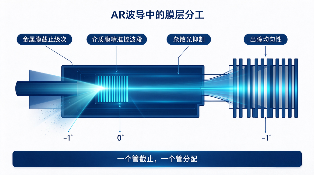
Division of Labor in AR Waveguides — Each Handles a Section of the Optical Path. In AR optical waveguide systems, metal films and dielectric films have clear divisions of labor. Metal films are responsible for "cutting off transmitted orders."
The coupling-in grating of a diffractive optical waveguide has an inherent contradiction: in grating diffraction, in addition to the +1 order light we need entering the waveguide, there is also 0 order transmitted light passing directly through and −1 order diffracted light leaking in the reverse direction. Such stray orders not only waste light energy but also generate stray light.
Coating a metal film on the grating surface can cut off useless transmitted orders and significantly improve coupling-in efficiency; the degree of improvement is affected by parameters such as grating period, film thickness, and wavelength.
Here the role of the metal film is not simply to enhance reflection, but to selectively allow effective diffracted light to pass. Dielectric films are responsible for "precise wavelength-band control." In scenarios such as multi-color beam combining, laser steering, and geometric waveguide semi-transmissive semi-reflective mirror arrays, dielectric films are the better choice.
By adjusting the combination of high- and low-refractive-index materials and the number of film layers, narrowband high-reflection coatings for specific wavelength bands can be customized. The core of geometric array optical waveguides is the multilayer semi-transmissive semi-reflective film array, and each layer must precisely control the reflection/transmission ratio to ensure uniformity of exit pupil expansion.
Geometric Array Waveguide: The Reflective Film Is the "Crucial Point"
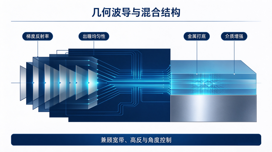
Compared with diffractive waveguides, geometric array optical waveguides depend more heavily on reflective films. The core structure of geometric waveguides is a multilayer semi-transmissive semi-reflective mirror array.
Light propagates forward inside the glass substrate by total internal reflection and is coupled out step by step upon encountering the mirror array. The reflectivity of each mirror layer directly determines how much light is coupled out at that position: if reflectivity is too high, the optical energy at the rear end is insufficient; if reflectivity is too low, the brightness of the front-end image is insufficient.
Image uniformity is achieved through precise design of the reflectivity gradient. Schott has built and put into operation a dedicated production line at its Kulim base in Malaysia, promoting geometric reflective waveguides from R&D to mass production; the core difficulty is maintaining stable and consistent coating quality across thousands of components.
According to Lumus official manufacturing materials, its waveguide manufacturing cooperation with Schott and Quanta has maintained a yield consistently above 95%, and coating and film stack deposition are core steps in the manufacturing process.
The reflective film of geometric waveguides is by no means simply coating a layer of silver film. It is necessary to precisely control the reflectivity of each layer piece by piece while ensuring coating consistency after large-batch stacking, which is also one of the hardest hurdles in mass production of geometric waveguides.
Hybrid Solution: Combining Strengths. In actual engineering implementation, hybrid film structures of metal + dielectric are very common. The metal layer provides basic broadband reflection capability, and dielectric thin films are stacked on top to further raise the reflectivity in the target wavelength band through interference effects.
In many public patent solutions, the first and second reflective layers can flexibly use dielectric layers or metal layers; the dielectric layer can be a single layer or a multilayer stack, and the metal layer provides baseline broadband reflection.
Core Selection Logic: First determine the reflection bandwidth, incidence angle range, and reflectivity specifications. For broadband high reflection, prioritize metals; for narrowband pursuit of ultimate reflection, choose dielectrics; if both broadband and high reflection are required, stack dielectric films for performance enhancement.
Conclusion: Metal films achieve reflection through free electrons, while dielectric films rely on thin-film interference. One type is "broad and sufficient," the other is "narrow and extreme."
In AR waveguide systems, metal films are used to block stray light that should not roam around, and dielectric films are used to finely control the light distribution ratio.
The essence of choosing a reflective film is determining whether this section of the optical path needs broader angle compatibility or extremely precise optical control.
Interactive Topic: In your AR waveguide solution, is the reflective film metal, dielectric, or a hybrid structure? What coating-related yield issues have you encountered? Welcome to leave a comment and share your experience.
[Risk Note] This article is an industry science popularization piece. The refractive index and reflectivity data in the text are typical reference values from public literature; actual coating effects are affected by film thickness, substrate, deposition process, and environment. Issues such as easy oxidation of metal films and angle drift of dielectric films need to be evaluated in optical simulation and sample verification, and final performance is subject to actual sample measurements.
—— AR Andy | Focused on the optical waveguide and AR microdisplay track, providing in-depth analysis of the underlying logic of the optical industry
-
![]()
Metal Film vs. Dielectric Film: The Selection Logic for AR Waveguide Reflective Coatings
-
![]()
Apple 'Wins Without Trying' Against NVIDIA
-
![]()
Nut Pandownload Ownership Change: The Logic of Large-Screen Projectors Replacing TVs Is Failing
-
Thanks to Chinese Support, Apple's China Revenue Surges 21%, with Revenue and Profit Hitting New Highs Again
-
![]()
Two-Trillion Sprint Tier: Benchmarking Analysis of Industries in Nanjing, Ningbo, Tianjin, and Qingdao
-
![]()
Cloud Computing in the AI Era: Prosperity for the Few | Juchao
-
![]()
Smartphone Specs Slashed Across the Board: Hardware Downgrades Leave Users in a Bind
-
![]()
Apple "Wins by Default" Against Nvidia