Diffraction or Scattering? The Two Physical Mechanisms Behind Stray Light in Optical Waveguides
 10/30 2026
 543

Abstract: Stray light in optical waveguides is not a single problem—it is a superposition of two distinct mechanisms. Diffraction arises from the periodic structure of gratings: it is ordered, calculable, and designable. Scattering arises from random defects such as surface roughness and uneven coating: it is disordered, cannot be precisely calculated, and can only be suppressed through process control. Without a clear boundary between the two, troubleshooting will only grow more chaotic.
Almost anyone doing R&D on AR optical waveguides has run into the "dirty image" problem. Rainbow patterns, ghost images, haze, and double images are often lumped together under the umbrella term "stray light." But trace the contamination back to its source, and it essentially splits into two completely different paths: diffraction or scattering? The two share similar physical origins, yet their engineering solutions are entirely different. Without this fundamental distinction, stray light troubleshooting can easily spiral into a vicious cycle—the more you adjust, the messier it gets.
Diffraction-Type Stray Light: Ordered, Calculable "Light Leakage"
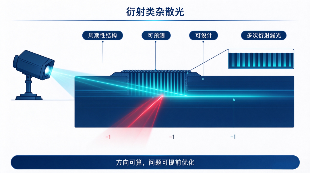
This type originates from the periodic structure of gratings or mirror surfaces. Its defining feature: under the assumption of an ideal period, the deflection direction of light can be deterministically predicted using the grating equation. The most typical source is multiple diffraction leakage caused by the in-coupling grating. Light from the projector enters the waveguide and, after first diffraction by the in-coupling grating, propagates through the waveguide.
But the in-coupling grating is no one-way light gate: light traveling through the waveguide by total internal reflection passes through the in-coupling grating region again, triggering secondary diffraction; part of the −1 order diffracted light escapes directly from the waveguide, forming stray light. The higher the grating diffraction efficiency, the stronger the out-coupling leakage—a relationship governed by Lorentz reciprocity.
Characteristics of this type of stray light: it is directly tied to grating diffraction efficiency and belongs to the category of problems that can be predicted and optimized in advance at the design stage. Beyond multiple diffraction leakage, diffraction-type stray light has three other typical scenarios.
Crosstalk stray light. In geometric waveguides, the angular offset of the in-coupling prism causes part of the light to be reflected by the mirrors in the vertical pupil expansion region and folded back to the horizontal pupil expansion region, where the two pupil expansion regions overlap and generate crosstalk stray light.
This type of stray light mostly appears only in the edge field of view and is difficult to eliminate completely. Zero-order reflection secondary imaging. When light emitted by the micro-image source hits the in-coupling grating, part of it undergoes zero-order (undiffracted) reflection, returns to the surface of the micro-image source, and after another reflection forms an offset ghost image. The industry commonly uses quarter-wave plates for polarization management to reduce the intensity of this type of stray light. Color light leakage.
The wavelength selectivity of the in-coupling grating has an upper limit. A grating designed for the central wavelength of green light still has partial diffraction response at the red and blue ends, causing color shift in the image. Optimization directions include improving the wavelength selectivity of the grating and adding interlayer isolation design in multilayer waveguides.
Scattering-Type Stray Light: Disordered Random Chaos That Can Only Be "Suppressed"
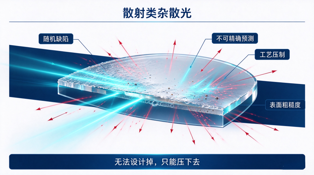
Scattering-type stray light comes from various random defects. Its defining feature: the deflection direction of light cannot be precisely predicted. Causes include microscopic roughness of lens surfaces, uneven coating thickness, impurities inside the substrate, residual burrs from cutting and polishing, bubbles in the bonding layer, and so on.
When light hits such irregular defects, it scatters randomly in all directions. Scattering-type stray light cannot be "designed away"—it can only be "suppressed." Corresponding engineering measures include tightening surface roughness specifications, improving coating uniformity, controlling cutting edge quality, and optimizing the bonding process. This category of problem falls outside the scope of optical design; it is a challenge at the manufacturing process level. Why is it so important to distinguish the two?
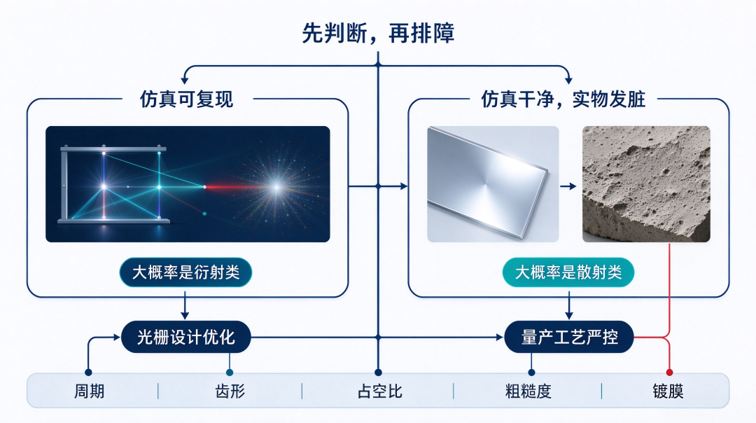
The core reason: the engineering solutions for the two types of stray light are completely different. Diffraction-type stray light is solved through grating design optimization—adjusting grating period, tooth shape, duty cycle, and the distribution of diffracted energy among orders.
Engineers can model, predict, and iteratively optimize directly in simulation software. Scattering-type stray light is solved through strict control of mass production processes—raising surface roughness standards, optimizing coating uniformity, and controlling cutting edge quality.
These parameters cannot be directly calculated using the grating equation; they can only be iteratively improved through process experiments and yield data in a closed loop. Many R&D teams fall into the dilemma of "the more you adjust, the messier it gets" precisely because they confuse the engineering boundaries between the two.
Using grating design to solve scattering problems, or using process optimization to solve diffraction problems—once the direction is wrong, no amount of investment will help.
Here is a simple rule of thumb: stray light that can be reproduced in simulation is most likely diffraction-type; if the simulated image is clean but the actual sample looks dirty, it is almost certainly scattering-type stray light.
Conclusion
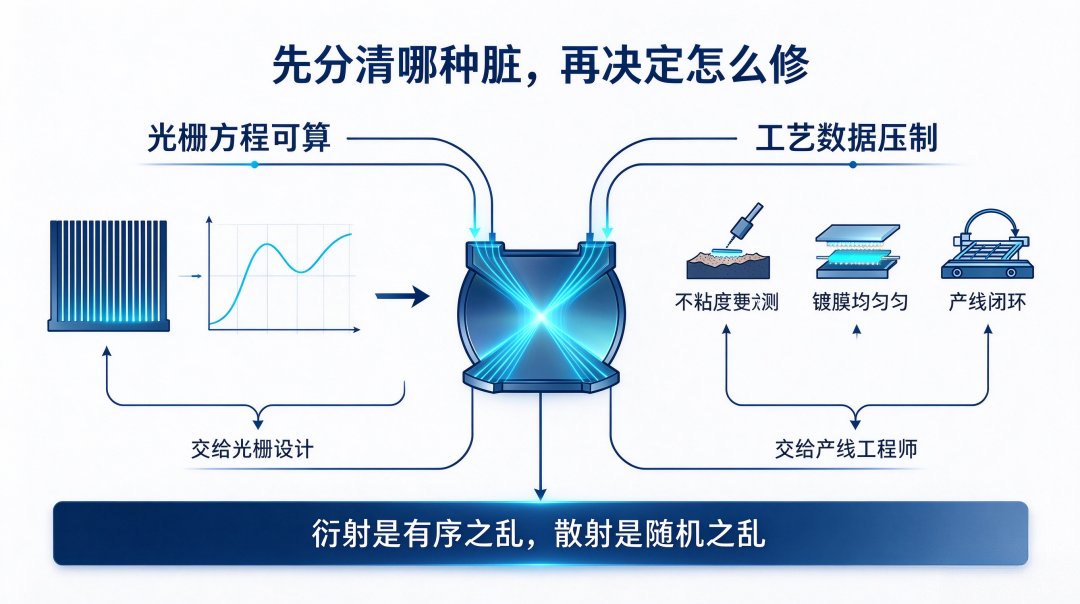
Stray light in optical waveguides is not a single fault but a superposition of two physical mechanisms: diffraction is ordered chaos; scattering is random chaos.
What can be calculated and predicted using the grating equation should be handled by grating design; what can only be continuously suppressed using process data should be handled by production line engineers. First determine "which kind of dirt it is," then decide "how to fix it."
Interactive topic: In your optical waveguide R&D or mass production, have you encountered diffraction-type stray light that "shows up in simulation," or scattering-type stray light where "the simulation is clean but the actual sample looks dirty"? Feel free to share your troubleshooting experience in the comments.
[Risk note] This article is an industry science popularization piece. The "diffraction/scattering" framework presented here is a practical framework for engineering troubleshooting, not a strict physical boundary: real gratings often contain mixed components of both; whether simulation can reproduce an issue depends on modeling accuracy; zero-order ghosting is essentially a ghost image. Actual troubleshooting requires comprehensive judgment combining simulation, process, and measurement.
—— AR Andy | Focused on the optical waveguide and AR microdisplay track, delivering in-depth analysis of the underlying logic of the optical industry
-
Mercedes-Benz's All-Electric E-Class
-
![]()
The Largest IPO in History Has Officially Filed Its Application
-
![]()
Prefabricated Data Centers Are Suddenly Catching On
-
![]()
Two Contrarian Bets: Can Wang Tao Really Succeed Zuckerberg?
-
![]()
Diffraction or Scattering? The Two Physical Mechanisms Behind Stray Light in Optical Waveguides
-
![]()
Solid-State Batteries: Policy Targets 2030, but Industry Leaders Say the Technology Is Only at Level 4
-
AI Is About to Dismantle America's Internet Toll Booths?
-
![]()
Phone Sales Hit a Ten-Year Low While Prices Keep Climbing—What's Going On?