LCoS and the Screen Door Effect: Why Do Our Eyes "Catch" the Pixel Gaps?
 11/18 2026
 532

Abstract: The screen door effect is not a matter of insufficient resolution—it occurs when the angular resolution of pixel gaps falls within the perceptible range of the human eye. LCoS reflective architecture inherently offers a high fill factor, but shrinking pixels brings fringing-field interference into play.
The screen door effect is a challenge common to all microdisplays, and each technology route has its own solutions. Seeing the grid is not because the screen is too small, but because the gaps are too large—or, put another way, because your eyes are too close.
In an earlier piece, The LCoS Fill Factor Trap: Why It Can Never Achieve True Black, we discussed the "failure to go black": light leaks through pixel gaps, and a pure black image turns into a hazy dark gray.
In this article, we look at another visual perception issue rooted in the same underlying problem: visible grids in the image. It is like looking through a screen window, with a neat grid pattern overlaid on the picture.
Frankly speaking, this is not low resolution; it is simply that the thin gaps between pixels happen to be captured by the human eye.
Let us clarify one thing first: the screen door effect is not unique to LCoS. Microdisplay solutions such as OLED, MicroOLED, and DLP also face the pixel gap issue; only the architectures and breakthrough approaches differ.
What Exactly Is the Screen Door Effect?
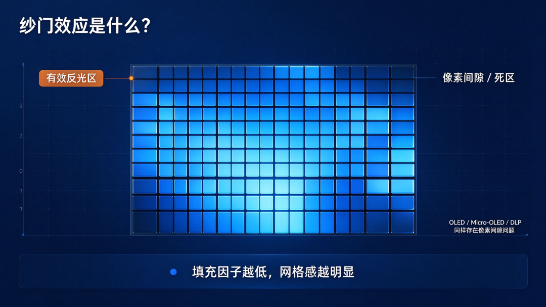
The screen door effect (SDE), simply put, is when the gaps between pixels are visible to the naked eye, adding a grid of intersecting black lines to the image.
Its root cause is not too few pixels, but the high proportion of pixel gaps within the entire pixel unit. This proportion is what we commonly call the fill factor: the ratio of the effective reflective area to the entire pixel area.
The lower the fill factor, the larger the ineffective gap area, and the more obvious the grid perception. One key point: the screen door effect is a visual perception issue, not a device failure. It does not cause color shift or significantly reduce brightness, but it severely damages immersion.
This is especially true with solid-color backgrounds and smooth gradients, where the grid pattern becomes particularly eye-catching.
When Can the Human Eye See This Gap? It Depends on Angular Resolution
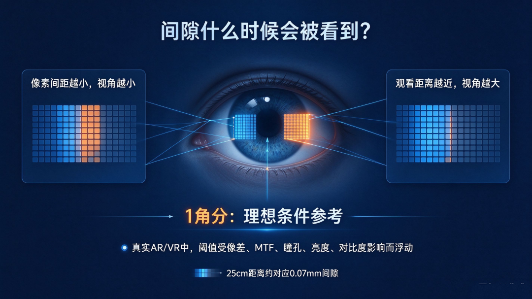
Whether the grid can be seen depends on one core factor: whether the viewing angle subtended by the pixel gap exceeds the resolution threshold of the human eye.
Many sources mention 1 arcminute, which is the theoretical limit of human eye cone cells under ideal laboratory conditions—converted into intuitive terms, it means being able to distinguish a gap of about 0.07 mm at a distance of 25 cm.
In real AR and VR optical paths, affected by optical aberrations, MTF, pupil size, image brightness, and contrast, this perception threshold fluctuates and cannot be directly used as a one-size-fits-all criterion.
This viewing angle is determined by two conditions: pixel pitch and viewing distance. The denser the pixels and the farther the viewing distance, the smaller the viewing angle subtended by the gaps, and the less likely we are to perceive the grid. In AR glasses, the situation is completely different.
AR optical engines are often only a few centimeters to tens of centimeters from the human eye, with an extremely short viewing distance. It is not that we want ultra-high PPI; it is that the distance to the eye is too close, and pixel gaps easily fall within the resolvable range of the human eye.
This is also the fundamental reason why AR has far higher pixel density requirements than phones and tablets.
LCoS's Inherent Advantage: Reflective Architecture Keeps Circuits Out of the Optical Area
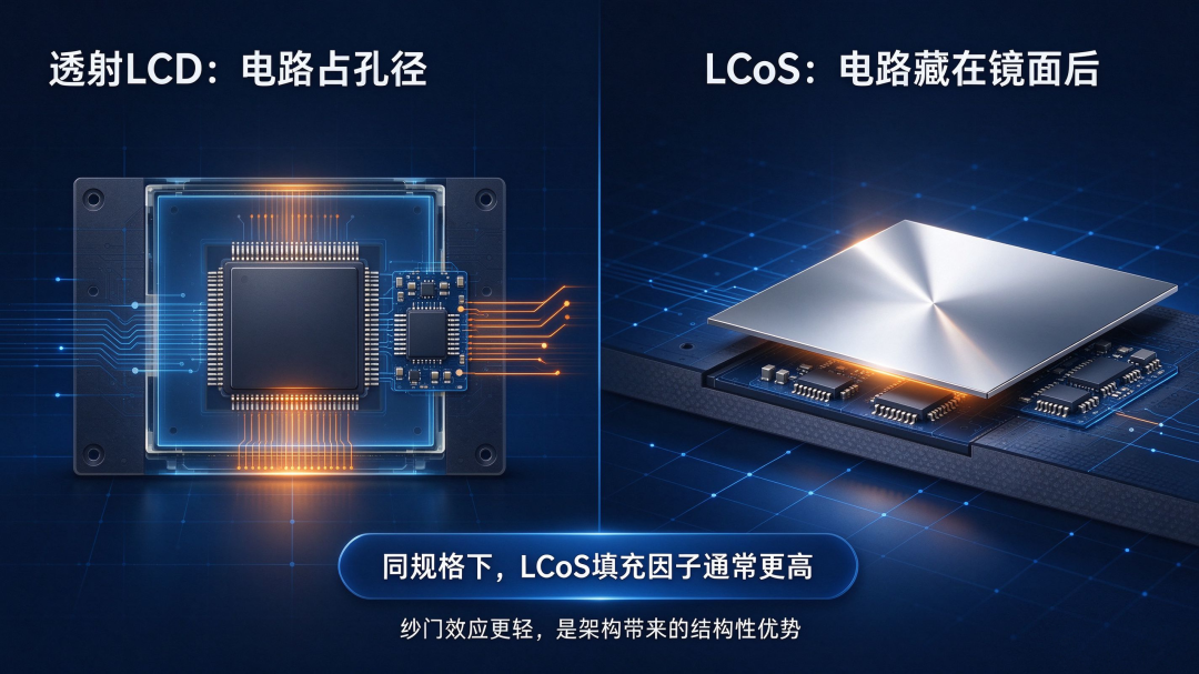
On the screen door effect issue, LCoS itself enjoys a bit of an inherent advantage thanks to its reflective architecture. In traditional transmissive LCD, driver circuits can only be placed beside the pixels, directly occupying the light-transmitting area, so the fill factor has an inherent ceiling.
LCoS, however, can bury the driver circuits behind the reflective mirror surface. Light reflects off the mirror, and the circuits do not occupy the reflective optical area. Under the same specifications, LCoS generally has a higher fill factor than transmissive LCD, and the grid perception of the screen door effect is theoretically much weaker.
This is also why LCoS still holds a place in the AR microdisplay race today. It is not necessarily the brightest solution, but when it comes to controlling pixel gaps, the architecture itself has an advantage.
The Bottleneck When Pixels Are Aggressively Scaled Down: The Fringing Field Effect

Many people think: then just make pixels smaller and denser, right? Reality is not that simple. When pixel size shrinks to roughly the same scale as the liquid crystal layer thickness, the influence of the fringing field effect emerges.
Electric fields between adjacent pixels crosstalk, and liquid crystal molecules at pixel edges cannot rotate to the designed angle as intended. The industry does have mature mitigation methods: adding shielding layers, optimizing drive waveforms, and selecting suitable liquid crystal materials to keep interference within a controllable range.
But process margins will continue to tighten as pixels scale down. Once control is lost, two problems appear: the effective reflective area actually usable by the pixel becomes smaller than designed, and the fill factor decreases instead of increasing; at the same time, electric field crosstalk causes color mixing between pixels, worsening image cleanliness.
Shrinking pixels is a feasible route, but it is not a mindless universal solution. The contradiction shifts from "circuits occupying area" to "electric fields crossing boundaries and interfering."
On the Engineering Side, There Are Mainly Three Approaches to Suppressing the Screen Door Effect

To suppress grid perception, the industry generally pursues three directions, each with its own trade-offs.
Increase fill factor: optimize the underlying CMOS driver layout and hide circuits further behind the reflective mirror; pair this with finer pixel isolation processes to reduce ineffective gap area.
(This route is most effective for LCoS, while OLED relies more on the architectural advantage of gap-free self-emissive pixels.)
Reduce pixel pitch: pack more pixels into the same display area and push the viewing angle subtended by the gaps into a range that is less likely to be perceived.
But this route is severely constrained by the fringing field effect and wafer process yield. Optical diffusion or microlens arrays: overlay microlenses or diffusion layers on the display surface to blur pixel gaps.
The cost is losing part of the MTF and optical efficiency, and microlens arrays require extremely high alignment precision, with very tight process tolerances for mass production.
To summarize once more: the screen door effect does not equal insufficient resolution; it essentially means that the viewing angle subtended by pixel gaps falls within the perceptible range of the human eye.
LCoS's reflective structure gives it decent inherent conditions. The edge interference caused by pixel scaling can be suppressed through multiple methods, but it will continue to compress design margins.
Once again, this is a problem that all microdisplay solutions must face together; only the optimization approaches differ among display routes. Seeing the grid is not because the screen is too small, but because the gaps are too large—or because your eyes are too close.
Discussion topic: In your AR display solution, is the screen door effect solved by increasing pixel density or by using optical diffusion for blurring? Feel free to leave a comment.
[Risk note] The 1 arcminute mentioned in the article is the ideal resolution limit of the human eye. In actual AR optical paths, the perception threshold fluctuates due to aberrations, MTF, pupil size, and brightness contrast; fill factor and fringing field effect are typical engineering reference values. Fringing fields can be suppressed through shielding layers, drive waveforms, and liquid crystal material selection; performance varies under different pixel architectures, liquid crystal materials, and viewing distances, and actual design and simulation verification shall prevail.
—— AR Andy | Focused on optical waveguides and the AR microdisplay track, providing in-depth analysis of the underlying logic of the optical industry
-
![]()
OpenAI Unveils GPT-6.2 Astra and Sol, Outperforming Claude Fable 5.2 at Just 5% of the Cost
-
![]()
Baidu's Q3 Report: Advertising Stalls as AI Takes the Wheel
-
![]()
JD.com: Retail Stops the Bleeding While Overseas Burns Cash — When Will the "Thrashing" End?
-
![]()
Great report! But without Jensen Huang, Nvidia just doesn't feel the same!
-
![]()
LCoS and the Screen Door Effect: Why Do Our Eyes "Catch" the Pixel Gaps?
-
![]()
Cybertruck Failed to Keep Musk, the Car Builder
-
![]()
Chips Are Scarce, Yet TSMC Has Started "Vetting Customers' Finances"?
-
After "Taking Down" Jensen Huang, the United States Officially Shows Its Hand: A Comprehensive Blockade on China's AI Computing Power