Revealing Satellite Internet: NG-RAN Architecture of NTN Satellites (Part 1)
 03/26 2026
 500
500
Preface
To support new interfaces and protocols required for NTN, with the premise of minimizing changes to NG-RAN, to facilitate technology inheritance and development, and to reduce R&D investment cycles.
3GPP discusses the NG-RAN architecture based on NTN in 38.821. It primarily discusses NG-RAN based on TP mode and NG-RAN based on OBP mode.
1. NG-RAN Architecture Based on TP Satellites 1.1 Overview
The TP satellite payload implements frequency conversion and RF amplification in both uplink and downlink directions. It corresponds to an analog RF repeater.
Thus, the satellite forwards the NR-Uu radio interface from the feeder link (between the NTN gateway and the satellite) to the service link (between the satellite and the UE).
The Satellite Radio Interface (SRI) on the feeder link is NR-Uu. In other words, the satellite does not terminate NR-Uu but merely acts as a repeater.
The NTN GW supports all necessary functions to forward signals over the NR-Uu interface.
Different TP satellites can be connected to the same ground gNB.
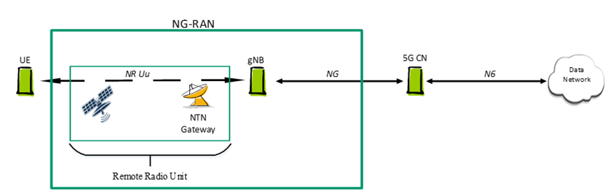 Figure 1: Network-RAN Architecture of TP Satellites 1.2 Detailed Architecture Description
The NG-RAN architecture based on TP satellites is shown in the figure below. The mapping to QoS flows is also highlighted.
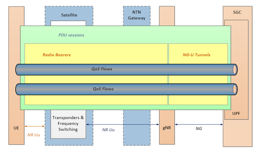 Figure 2: NG-RAN Mapping to QoS Flows Based on TP Satellites
The UE accesses the 5G system through a 3GPP NR-based radio interface.
The user plane protocol stack is described below.
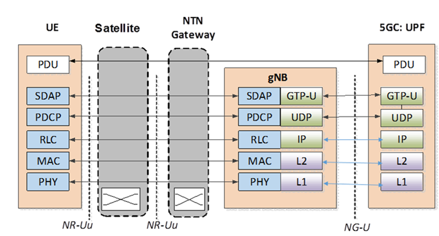 Figure 3: User Plane Protocol Stack (TP Satellite)
User data is transmitted between the UE and the 5GC as usual, but via the NTN gateway.
The control plane protocol stack is described below.
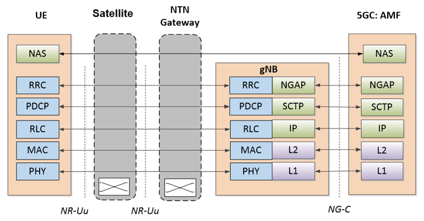 Figure 4: Control Plane Protocol Stack (TP Satellite)
NAS signaling from the UE and NG-AP signaling from the gNB are transmitted to the 5GC, and vice versa.
1.3 NG-RAN Impact
Supporting TP satellite access does not require modifications to the NG-RAN architecture.
NR-Uu timers may need to be extended to accommodate the long delays of the feeder link and service link. In LEO scenarios with ISL, the delay to be considered should include at least the feeder link and one or more ISLs.
Both CP and UP protocols are on the ground.
CP, apart from the need to adapt to longer round-trip times on Uu, does not pose any particular issues in this scenario. This can be addressed through implementation.
UP, apart from the impact on UP packets due to longer round-trip times, the data plane protocol itself is unaffected. Longer delays on the Uu interface will require more buffering of UP packets in the gNB.
2 NG-RAN Architecture Based on Regenerative Satellites 2.1 gNB-Processed Payload 2.1.1 Overview
The NG-RAN logical architecture described in TS 38.401 serves as the baseline for NTN scenarios.
The satellite payload regenerates the signals received from Earth.
The NR-Uu radio interface on the service link between the UE and the satellite.
The Satellite Radio Interface on the feeder link between the NTN gateway and the satellite.
The SRI is the transmission link between the NTN GW and the satellite.
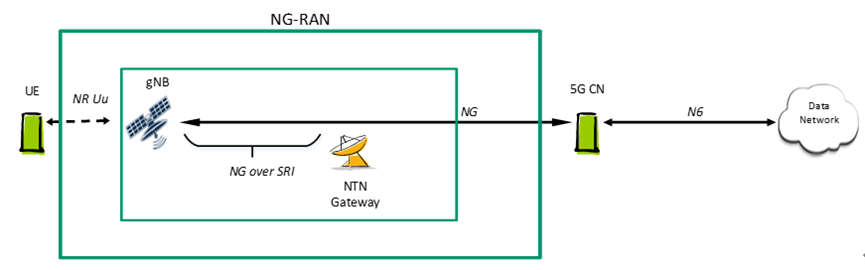 Figure 5: Regenerative Satellite without ISL, gNB-Processed Payload
The satellite payload also provides inter-satellite links between satellites.
The ISL is the transmission link between satellites. The ISL can be an RF interface or an optical interface, and can be defined by 3GPP or non-3GPP, but this is beyond the scope of the study project.
The NTN GW is a transport network layer node and supports all necessary transport protocols.
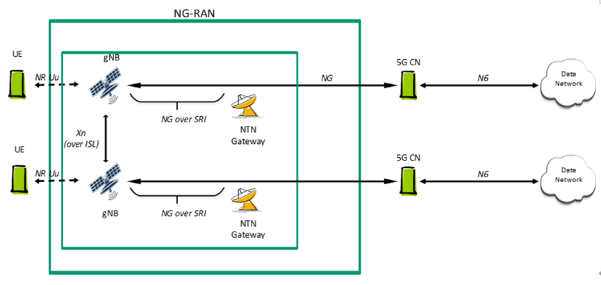 Figure 6: Regenerative Satellite with ISL, gNB-Processed Payload
The figure above illustrates that UEs served by onboard gNBs can access the 5GCN via ISL.
gNBs on different satellites can be connected to the same ground-based 5GCN.
If a satellite carries multiple gNBs, the same SRI will transmit all corresponding NG interfaces.
2.1.2 Detailed Architecture Description
The NG-RAN architecture based on regenerative satellites is shown in the figure below. The mapping to QoS flows is also highlighted.
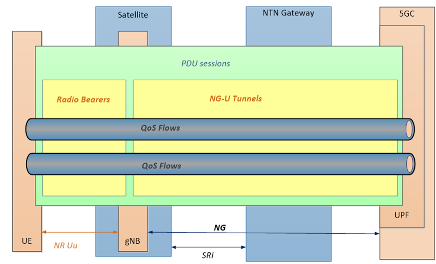 Figure 7: NG-RAN Architecture Based on Regenerative Satellites (Onboard gNB) and QoS Flows
The UE user plane protocol stack for PDU sessions is described below.
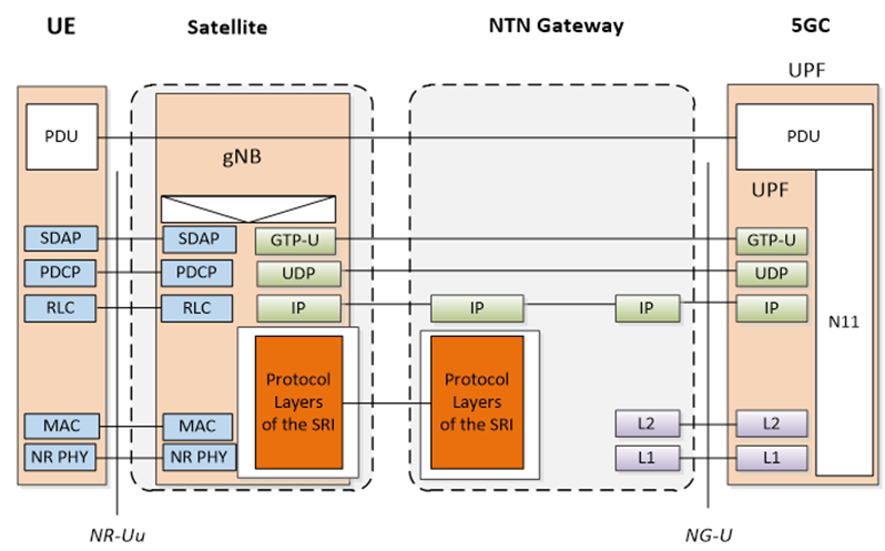 Figure 8: NG-RAN Protocol Architecture for Regenerative Satellites (Onboard gNB): User Plane
The protocol stack for the Satellite Radio Interface is used to transmit the UE user plane between the satellite and the NTN gateway.
User PDUs are transmitted as usual between the 5GC and the onboard gNB via GTP-U tunnels, but via the NTN gateway.
The UE control plane protocol stack for PDU sessions is described below.
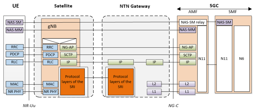 Figure 9: NG-RAN Protocol Architecture for Regenerative Satellites (Onboard gNB): Control Plane
NG-AP is transmitted as usual between the 5GC and the onboard gNB via SCTP, but via the NTN gateway.
The NAS protocol is also transmitted as usual by the NG-AP protocol between the 5GC and the onboard gNB, via the NTN gateway.
2.1.3 NG-RAN Impact
NG Application Protocol timers may need to be extended to accommodate the long delays of the feeder link.
NG (compared to terrestrial networks) may experience longer delays (up to several hundred milliseconds in the case of GEO satellites), which will affect both CP and UP; this can be addressed through implementation. In LEO scenarios with ISL, the delay to be considered should include at least the feeder link and one or more ISLs.
2.2 gNB-DU-Processed Payload 2.2.1 Overview
The NG-RAN logical architecture with CU/DU separation described in TS 38.401 serves as the baseline for NTN scenarios.
The satellite payload regenerates the signals received from Earth.
The NR-Uu radio interface on the service link between the satellite and the UE.
The Satellite Radio Interface on the feeder link between the NTN gateway and the satellite. The SRI transmits the F1 protocol.
The satellite payload can provide inter-satellite links between satellites.
The SRI is the transmission link; the logical interface F1 they transmit is specified by 3GPP.
The NTN GW is a transport network layer node and supports all necessary transport protocols. DUs on different satellites can be connected to the same ground-based CU.
If a satellite carries multiple DUs, the same SRI will transmit all corresponding F1 interface instances.
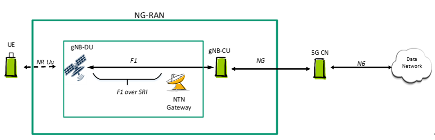 Figure 10: NG-RAN Based on gNB-DU for Regenerative Satellites 2.2.2 Detailed Architecture Description
The NG-RAN architecture based on regenerative satellites is shown in the figure below. The mapping to QoS flows is also highlighted.
PDCP PDUs are transmitted by the SRI protocol stack.
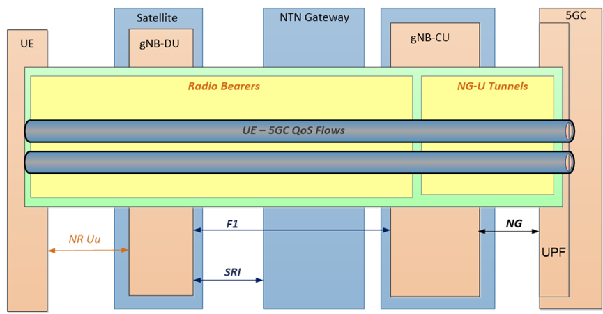 Figure 11: NG-RAN Architecture Based on Regenerative Satellites (Onboard gNB-DU) and QoS Flows
The UE user plane protocol stack for PDU sessions is described below.
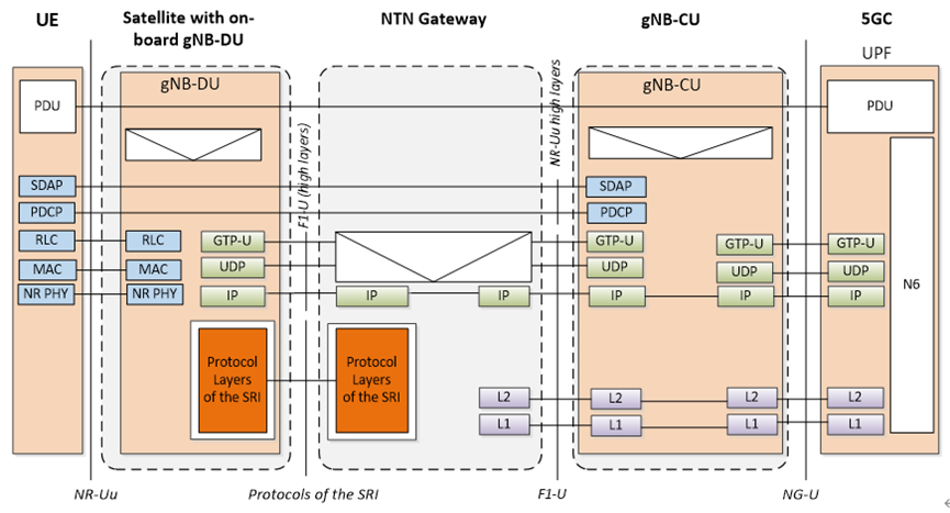 Figure 12: NG-RAN Protocol Architecture for Regenerative Satellites (Onboard gNB-DU): User Plane
The protocol stack for the Satellite Radio Interface is used to transmit the UE user plane between the satellite and the NTN gateway.
User PDUs are transmitted via GTP-U tunnels between the 5GC and the gNB-CU.
User PDUs are transmitted via GTP-U tunnels between the gNB-CU and the onboard gNB-DU via the NTN gateway.
The UE control plane protocol stack for PDU sessions is described below.
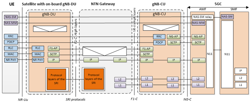 Figure 13: NG-RAN Protocol Architecture for Regenerative Satellites (Onboard gNB-DU): Control Plane
NG-AP PDUs are transmitted via SCTP between the 5GC and the gNB-CU.
RRC PDUs are transmitted via the F1-C protocol stack (based on PDCP) between the gNB-CU and the onboard gNB-DU, via the NTN gateway. F1-C PDUs are transmitted via SCTP over IP. IP packets are transmitted via the SRI protocol stack on the SRI and any L2/L1 layers between the gNB-CU and the NTN GW.
The NAS protocol is also transmitted by the NG-AP protocol between the 5GC, gNB-CU, and the onboard gNB-DU, via the NTN gateway.
2.2.3 NG-RAN Impact
RRC and other Layer 3 processing are terminated in the ground-based gNB-CU and are subject to stricter timing constraints.
Using this architectural option for LEO systems or even GEO may impact current F1 implementations (e.g., timer extensions). The impact on LEO is much less significant than on GEO.
In this architecture, all CP interfaces pointing to ground-based NG-RAN nodes are terminated on the ground.
CP, apart from the need for F1AP to adapt to longer round-trip times on the SRI, does not pose any particular issues in this scenario.
UP, instances running on Xn are unaffected by the presence of NTN, while instances running on F1 (transmitted via SRI) will need to adapt to longer round-trip times on the SRI. This, in turn, will require more buffering of UP packets in the gNB-CU.
-
![]()
ByteDance, DJI, and Xiaohongshu Secure Top Three Positions Among China’s Fastest-Growing Unicorns
-
Tesla's in-car voice system in China is finally learning to 'understand human language'
-
![]()
Foreigners Are Amazed: Chinese Electric Vehicle Drive Systems Unveil Innovative 'Poses'
-
![]()
700,000 Brothers and the Future of Robots: Behind JD.com's 'Nirvana Plan'
-
![]()
Zhipu's Trillion-Dollar Valuation: A New Chapter for China's AI
-
![]()
Is Laifen, a 'Dyson Alternative' on the Rise, Now Ensnared by the 'Alternative Curse'?
-
![]()
Beyond Patents: Insta360 and DJI Compete in Retail
-
![]()
Piercing Through Industry Chaos: The Curtain Rises on Compliance for Autonomous Driving