Satellite Internet: Exploring NTN Antenna Polarization
 06/23 2026
 349
349
At present, China is making significant strides in constructing its 'Next-Generation Communication Network.' Meanwhile, the 3GPP is actively deliberating on international standards for 6G physical layer waveforms and satellite internet air interfaces. It is anticipated that 6G will achieve commercialization by 2030.
It is noteworthy that, currently, both international projects like StarLink and domestic initiatives such as Guowang and Qianfan constellations are proceeding with their satellite internet deployments as planned. The envisioned network architecture comprises ground user terminals, NTN satellite payloads, and gateway stations, which together will form a comprehensive 'space-air-ground-sea' global coverage network. Among these components, the NTN satellite payload stands out as a core element, encompassing sophisticated signal processing capabilities and phased array antennas.

The NTN satellite system has the capability to employ advanced antennas to generate multiple beams on the ground. To minimize inter-cell interference, frequency reuse strategies (with a frequency reuse factor, FRF, greater than 1) can be implemented. Although spatial frequency reuse technology enhances the Signal-to-Noise Ratio and Interference-to-Noise Ratio (SINR), it inherently imposes limitations on the bandwidth and system capacity of each beam. For instance, the traditional frequency reuse-3 (FRF-3) scheme effectively curbs inter-cell interference; however, each cell is restricted to utilizing only one-third of the available spectrum resources. Taking the S-band as an example, under full frequency reuse conditions (FRF = 1), each cell is allocated a 30 MHz bandwidth. Conversely, in FRF-3 mode, each cell's bandwidth is reduced to 10 MHz, as the system bandwidth is distributed among three adjacent cells to mitigate interference.
To augment the bandwidth of each beam while maintaining adequate isolation and minimizing interference between beams, a hybrid approach combining polarization multiplexing and frequency reuse can be adopted, as illustrated in Figure 1. This strategy involves adjacent cells utilizing different polarization modes, namely Right-Hand Circular Polarization (RHCP) and Left-Hand Circular Polarization (LHCP). The Release-16 version of NR solutions supporting NTN highlights the benefits of providing polarization mode information for NTN signals, particularly when User Equipment (UE) can differentiate between RHCP and LHCP through circularly or linearly polarized antennas.
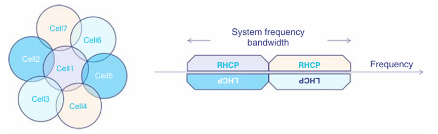
Figure 1: Polarization Multiplexing Scheme in Conjunction with Frequency Reuse
NR NTN Release-17 delineates the polarization type indication for downlink transmission at the satellite end and the corresponding indication for uplink reception. It introduces two RRC parameters pertaining to polarization in NR NTN:
ntn-PolarizationDL: This parameter conveys the polarization information for downlink transmission on the service link, encompassing Right-Hand Circular Polarization (RHCP), Left-Hand Circular Polarization (LHCP), and Linear Polarization. The specified polarization information pertains to the type employed by the satellite end for downlink transmission.
ntn-PolarizationUL: This parameter is utilized to indicate the polarization information for the uplink service link. In instances where this parameter is unspecified while ntnPolarizationDL is specified, the UE assumes that the same polarization is utilized for both uplink and downlink transmissions. The indicated polarization information refers to the type used by the satellite end for uplink reception.
Moreover, NTN Release-17 facilitates polarization signal transmission for the target serving cell in handover command messages and for non-serving cells in RRM measurement configurations.
As stipulated in 3GPP TS 38.306, UE support for polarization signaling in NR NTN is optional. This signaling encompasses the following functional components:
- Support for polarization indication reception in SIB, utilizing corresponding polarization type parameters to denote DL and/or UL polarization information: RHCP, LHCP, or linear polarization;
- Support for polarization signals for the target serving cell in handover command messages;
- Support for polarization signals for non-serving cells in RRM measurement configurations.
---
-
![]()
Over 50% of Revenue Hinges on Yutong Optics! This Optical Equipment Manufacturer is Charging Towards an IPO
-
![]()
YOCO Optics Finalizes Industrial and Commercial Registration Update Post 160 Million Yuan Investment in Jiangfeng Biology, Securing 20% Stake to Emerge as Second-Largest Shareholder!
-
![]()
Google Market Value Plummets by $1.5 Trillion Overnight Following the Loss of Two Key Figures
-
![]()
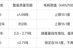
Put an End to the EV 'Weight Gain Race'! Can Your Car Still Be Driven Under the New National Standards?
-
![]()
In 2026, 'AI Upstarts' Collectively Bet on World Models
-
![]()
【OFweek Weike Cup】Phoenix Optics Officially Participates in the 2026 Optical Industry Annual Innovation Product Award
-
![]()
Ford Ditches Mach-E: Will Its Billion-Dollar Electrification Drive Have to Start All Over Again?
-
![]()
【OFweek Weike Cup】Shuangli Hepu Officially Participates in the 2026 High-Growth Enterprise Award in the Optical Industry