Satellite Earth Observation Radar: From SAR to Intelligent Sensing with FPGA
 08/18 2026
 475
475
Preface
Synthetic Aperture Radar (SAR) represents the most powerful active microwave remote sensing tool for space-based Earth observation, capable of delivering high-resolution surface imaging under all-weather and all-time conditions. Over three decades, European SAR technology has evolved from ERS-1 to Sentinel-1 across three generations and is now at the cusp of a new breakthrough in addressing the inherent conflicts between resolution, coverage width, and data rate.
This article systematically reviews the architectural evolution, core applications, digital beamforming (DBF)-enabled expansion of traditional performance boundaries, engineering challenges in digital backends, emerging trends in New Space commercialization, and frontier directions in cognitive remote sensing, based on the European Space Agency (ESA)'s 2023 report, Satellite radio-frequency payloads and instruments Overview and challenges.
Using Sentinel-1 as a baseline case, along with future missions such as ROSE-L, Sentinel-1 NG, and the onboard Radio Frequency Interference (RFI) processing practices of the CIMR radiometer, the article provides a comprehensive overview of the technological landscape and development trends in spaceborne radar remote sensing. High-performance FPGAs play a pivotal role in onboard payload signal processing, imaging algorithms, and data compression.
I. Introduction: From ERS-1 to the Data Deluge Era
In 1991, Jean-Marie Luton, then ESA Director General, wrote upon the launch of ERS-1: "Observing Earth from space is essential for understanding the Earth system... This is crucial for comprehensively assessing the environmental impacts of human activities." Over three decades later, the foresight of this statement has become increasingly evident—evidence of anthropogenic climate change continues to accumulate, with its effects now visible on a global scale. Satellite remote sensing, with its unique advantage of "providing globally consistent data from a single instrument and avoiding cross-calibration issues," has become an indispensable tool for environmental monitoring.
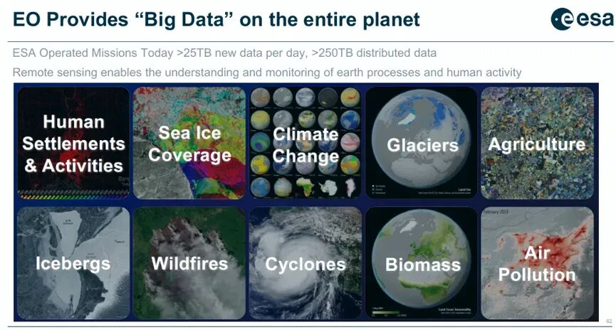
However, remote sensing in low Earth orbit faces an eternal trade-off between spatial and temporal resolution: high-resolution imaging typically implies narrow swath widths and long revisit periods, while wide-area monitoring requires sacrificing spatial detail. New-generation missions and user demands call for broader coverage, improved radiometric and geometric performance, shorter revisit intervals, and lower data latency—all pointing toward a single imperative: more data. Currently, ESA's operational missions generate over 25 TB of new data daily, with distribution volumes exceeding 250 TB/day, and these figures continue to grow rapidly.
In frequency selection, spaceborne radars must comprehensively consider ITU frequency allocations, antenna size (determining beamwidth and gain), propagation effects (atmospheric attenuation and ionospheric impacts), range and Doppler ambiguities, and the technological maturity of microwave components. Typical frequency bands and their applications include: P-band (300 MHz-1 GHz) for biomass and soil moisture; L-band (1-2 GHz) for agriculture, forestry, and soil moisture; C-band (4-8 GHz) for marine, land, and agricultural monitoring; X-band (8-12 GHz) for high-resolution imaging; and Ku/Ka-band for snow and ice as well as ocean observations. ITU-allocated bandwidths for Earth observation radars in each band are: P-band 6 MHz, L-band 85 MHz, S-band 150 MHz, C-band 320 MHz, X-band 600 MHz, Ku-band 500 MHz, and Ka-band 500 MHz.
II. Synthetic Aperture Radar System Architectures and Evolution2.1 Fundamentals of SAR
SAR leverages the motion of a satellite platform along its trajectory to transmit and receive pulses at different azimuth positions, coherently synthesizing a virtual aperture much longer than the physical antenna through processing, thereby achieving extremely high azimuth resolution. To maintain coherence, the following conditions must be met:
The Pulse Repetition Frequency (PRF) must be sufficiently high to ensure that the same target remains within the antenna's main beam across consecutive pulses; the echo time window must cover the target's range extent, with typical Earth observation SARs employing a Pulse Repetition Interval (PRI) of approximately 0.7 ms and echo times around 5-6 ms; and the antenna's along-track length, in conjunction with the PRF, jointly determines azimuth ambiguity performance. 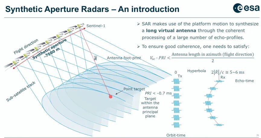
2.2 Three Generations of European C-Band SAR
Europe has accumulated over three decades of experience in C-band SAR development, showcasing a complete technological leap from mechanically scanned to electronically scanned active phased arrays:
GenerationRepresentative ModelKey TechnologiesPerformance ParametersFirst GenerationERS-1/2Passive waveguide slot array, single-polarization antenna 10 m × 1 m, bandwidth 15 MHz, resolution 26 m × 30 m (range × azimuth), swath width 100 km, no elevation scanning capabilitySecond GenerationEnviSat ASARActive phased array, dual-polarization 320 T/R modules × 10 W, antenna 10 m × 1.3 m, bandwidth 16 MHz, swath width 100-400 km (ScanSAR), with elevation scanning capabilityThird GenerationSentinel-1Active phased array, dual-polarization 560 T/R modules × 16 W, antenna 12.3 m × 0.84 m, bandwidth 100 MHz, swath width 80-400 km, supporting ScanSAR and TOPS modes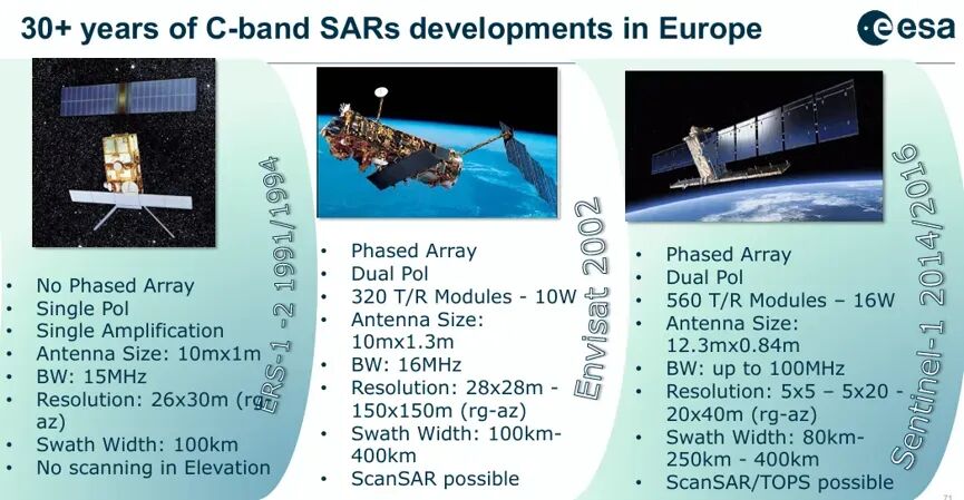
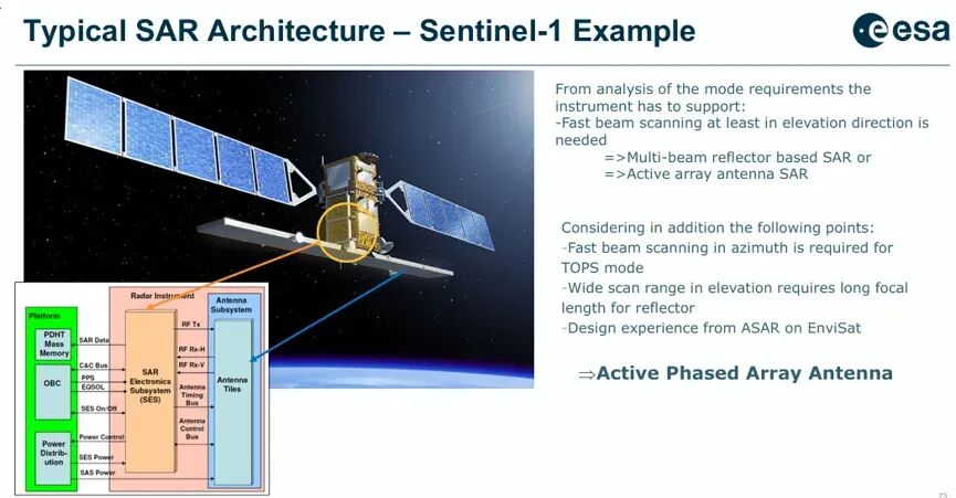
The design choices for Sentinel-1 are highly representative. From a mode requirements perspective, the instrument must support rapid elevation beam scanning (for ScanSAR and TOPS) as well as azimuth beam steering (for azimuth scanning in TOPS mode). Technically, two paths were considered: "multi-beam reflector SAR" and "active phased array SAR." However, the reflector solution requires a long focal length to accommodate wide elevation scanning ranges and has limited azimuth scanning capability. Considering EnviSat ASAR's design experience and the unique demands of TOPS mode, Sentinel-1 ultimately adopted an active phased array antenna.
2.3 Fundamental Radar Architectures
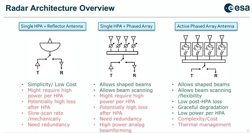
From the perspective of transmit chain and antenna combinations, spaceborne radar architectures can be classified into three categories:
Single HPA + Reflector Antenna: Simple structure and low cost, but each HPA must handle high power, resulting in significant post-HPA losses, slow scanning rates (mechanical scanning), and the need for redundancy.
HPA Array + Reflector: Enables shaped beams and beam scanning but still requires high-power HPAs with post-HPA losses, necessitating analog beamforming and redundant design.
Direct Radiating Active Phased Array (DRA): Offers flexibility in beam shaping and rapid scanning, with low post-HPA losses (T/R modules adjacent to radiating elements), lower power per element, and graceful degradation (partial element failures only marginally affect performance). The trade-off is high system complexity and thermal management challenges. Sentinel-1 belongs to this category.
III. SAR Applications and Sentinel-1's Representative Modes3.1 Core Application Domains
SAR data finds applications across a broad spectrum of land and ocean monitoring:
Land Monitoring: Soil moisture retrieval (via backscatter coefficient and incidence angle relationships), agricultural crop type identification and growth monitoring, forest biomass estimation; Disaster Response: Flood mapping (leveraging low backscatter from water bodies in SAR images), earthquake deformation measurement (Differential Interferometric SAR, DInSAR), volcanic activity monitoring (through cumulative deformation time series); Ocean Monitoring: Sea ice extent and drift, ship detection, oil spill monitoring, and ocean wave spectrum retrieval. 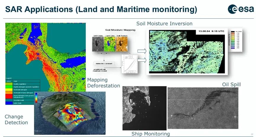
In interferometric SAR (InSAR), Sentinel-1's short revisit period (6 days) and high orbit control accuracy make it the tool of choice for global deformation monitoring. A Typical cases include l example is the 7.4-magnitude earthquake in Oaxaca, Mexico, on June 23, 2020—interferometric processing of pre- and post-earthquake SAR images generated a line-of-sight deformation map, with red areas indicating movement toward the satellite and blue areas indicating movement away, providing critical constraints for seismic source mechanism inversion.
In disaster response, during the 2022 Pakistan monsoon floods, Sentinel-1 data was rapidly processed to generate flood extent maps—rainfall intensity reached 9-10 times the annual average, inundating vast areas nationwide and affecting millions. SAR's all-weather imaging capability proved particularly vital under such cloudy and rainy conditions. For volcanic monitoring, cumulative deformation time series from 2015-2020, combined with machine learning algorithms, enabled predictive mapping of eruption probabilities for Galápagos Islands volcanoes.
3.2 Imaging Modes of Sentinel-1
Sentinel-1 offers multiple imaging modes tailored to different application needs:
Stripmap Mode (SM): Fixed beam pointing, providing the highest resolution (5 m × 5 m) with an 80 km swath width, suitable for detailed local observations; Interferometric Wide Swath Mode (IW): Employs TOPS (Terrain Observation with Progressive Scans) technology for simultaneous azimuth and elevation scanning, achieving a 250 km swath width and 5 m × 20 m resolution, serving as the primary mode for interferometry and wide-area monitoring; Wave Mode (WV): Collects 20 km × 20 km sub-swaths at regular intervals along the orbit for ocean wave spectrum retrieval, with a low transmission duty cycle. 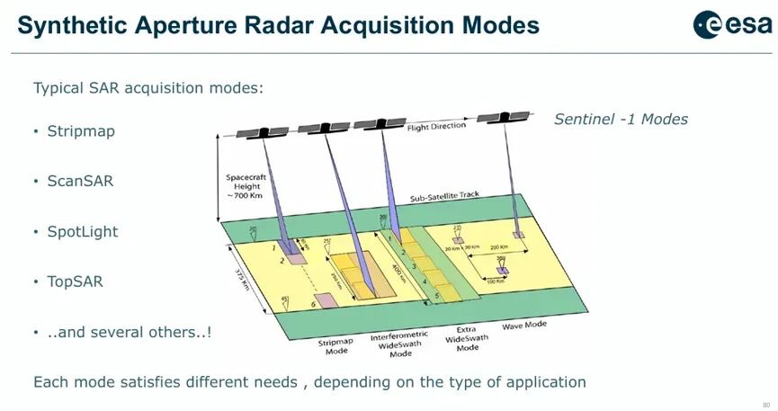
IV. Digital Beamforming's Expansion of SAR Performance
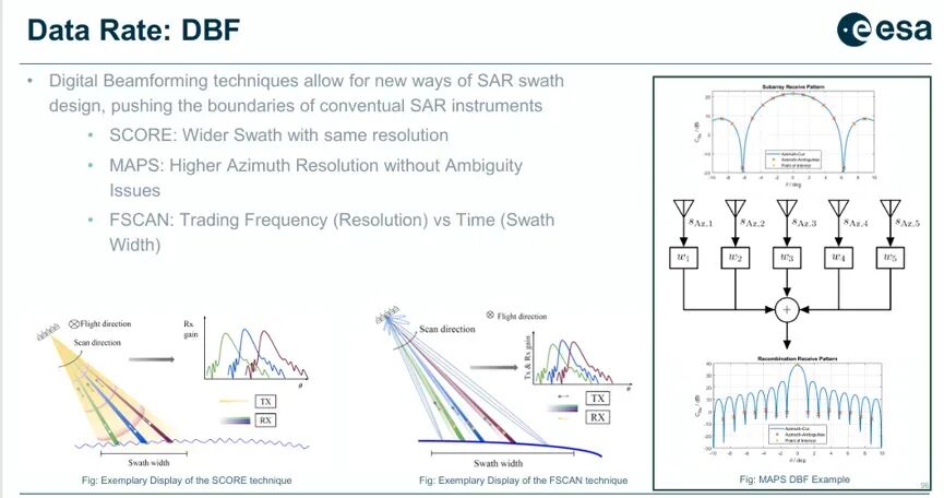
Digital beamforming is fundamentally transforming the design space of SAR systems, breaking through the traditional rigid constraints between resolution and swath width.
4.1 SCORE (Scan-On-REceive)
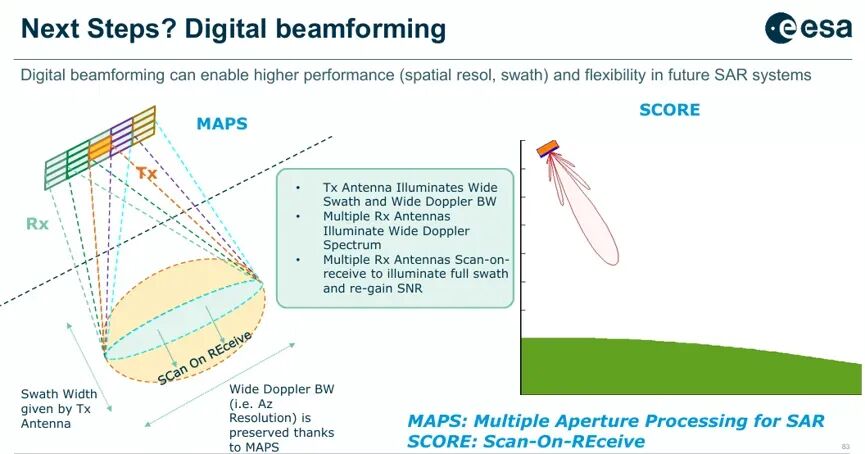
SCORE technology utilizes DBF to rapidly electronically scan the elevation beam during reception, ensuring it continuously tracks echo signals from ground targets at varying ranges. Its core value lies in:
Signal Energy Recovery: By increasing receive antenna gain, it compensates for insufficient transmit power, reducing the instrument's reliance on high-power HPAs; Ambiguity Performance Improvement: Suppresses interference signals from range-ambiguous regions through spatial filtering; Extremely High Scanning Speed: Elevation beam scanning rates must reach approximately 0.1 degrees per microsecond; Frequency Dispersion Compensation: Broadband signals require frequency dispersion introduction in the receive beam to avoid pulse spreading losses. 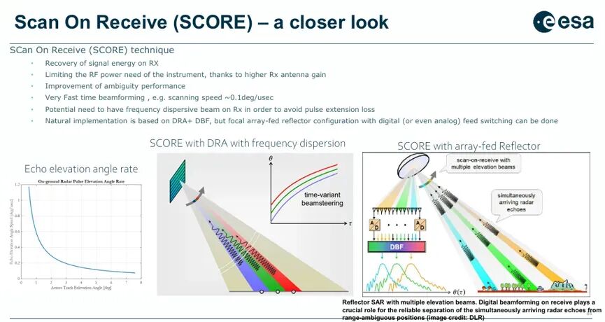
The natural implementation for SCORE is "DRA + DBF," but it can also be achieved through array-fed reflectors combined with digital (or analog) feed switching.
4.2 MAPS (Multi-Aperture Processing) and Azimuth Ambiguity Suppression
In the azimuth direction, MAPS technology divides the receive antenna into multiple sub-apertures, forming multiple receive beams through DBF. Specifically:
A wide transmit beam (azimuth) illuminates the desired swath width, but due to its width, ambiguous signals (from adjacent pulse periods) are also received with high gain; After multi-channel reception, complex weighting and recombination of the five azimuth channels can perfectly suppress the first four ambiguous signals while maintaining the desired signal gain; The equivalent effect is achieving both high azimuth resolution and wide swath width through DBF while maintaining a high PRF to avoid azimuth ambiguities. 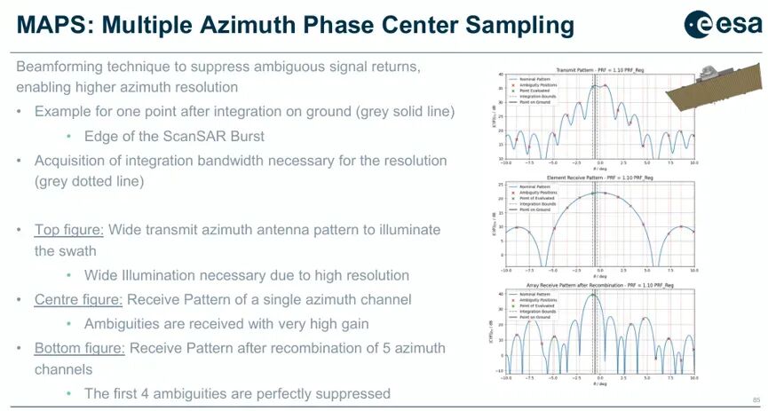
4.3 FSCAN: Flexible Trade-off Between Frequency and Time
FSCAN technology allows dynamic trade-offs between frequency resolution (range direction) and scan time (swath width), optimizing system parameters according to different mission requirements.
4.4 Re-evaluation of Planar Antennas and Reflector Antennas
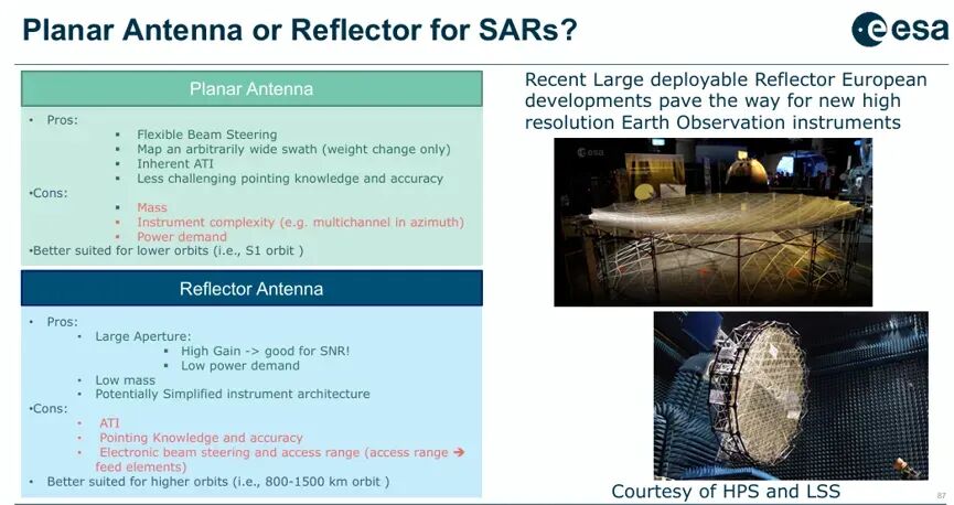
The maturation of DBF technology has reopened the traditional choice between planar antennas and reflector antennas:
Planar Antenna (DRA) Advantages include flexible beam pointing, support for arbitrarily wide swaths (at the cost of increased mass), inherent along-track interferometry (ATI) capability, and lower pointing accuracy requirements. Disadvantages include high mass, complex instrumentation (multi-channel), and high power consumption. More suitable for low Earth orbit (e.g., Sentinel-1's ~700 km orbit).
Reflector Antenna Advantages include high gain from large aperture (beneficial for SNR), low power consumption, light mass, and potentially simpler instrument architecture. Disadvantages include limited ATI capability, stringent pointing accuracy requirements, and restricted electronic scanning angle range. More suitable for high Earth orbit (800-1500 km). Recent technological advancements in large deployable reflectors in Europe have paved the way for a new generation of high-resolution EO instruments.
For future missions, large-aperture reflector antennas combined with array feeding and DBF are becoming highly attractive solutions, offering a balance of high gain, low power consumption, and flexibility.
5. Future SAR Missions and Performance Leap 5.1 Key Requirements for Next-Generation SAR Missions
Future SAR missions (e.g., ROSE-L, Sentinel-1 NG) impose higher demands on imaging performance:
Larger antenna aperture (reflector or enhanced DRA) to improve gain and resolution; wider operational bandwidth (>100 MHz) to support high resolution; multi-channel reception (elevation × azimuth) to support SCORE and MAPS; digital beamforming capability as a standard configuration; slow-varying/random PRI (Staggered PRI) technology to avoid interference and ambiguity.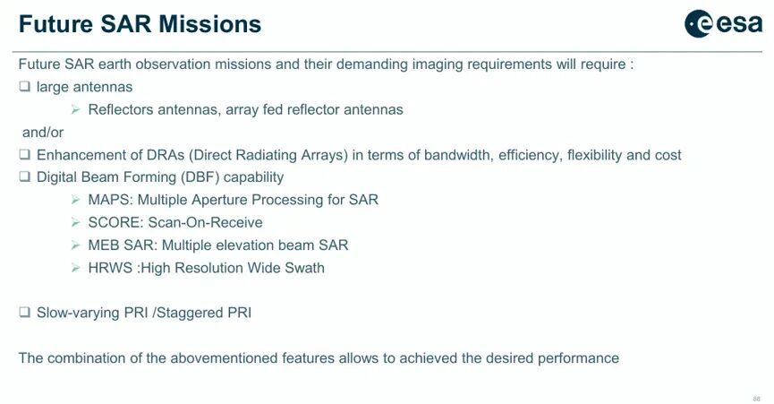
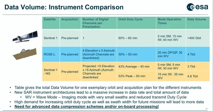
In terms of data volume, a comparison of single-orbit data volumes for three typical instruments is as follows:
Satellite Number of Digital Channels (per polarization) Orbit Duty Cycle Typical Operating Mode Time Allocation Single-Orbit Data Volume Sentinel-1 1 (conventional) 60% – 60 minutes SM 5 min, IW 15 min, WV 40 min >400 Gbit ROSE-L 4 (elevation) × 5 (azimuth) downlink 50% – 50 minutes DP/QP 20 min, WV 30 min 4 Tbit Sentinel-1 NG (expected) >5 (elevation) × >5 (azimuth) downlink 43% average – 40 min / 53% peak – 50 min SM/IW/WV combination 3-4.8 Tbit
It is evident that data volume has increased by an order of magnitude, necessitating research into advanced data compression methods and onboard processing.
5.2 Derivation of Data Rate Upper Bound
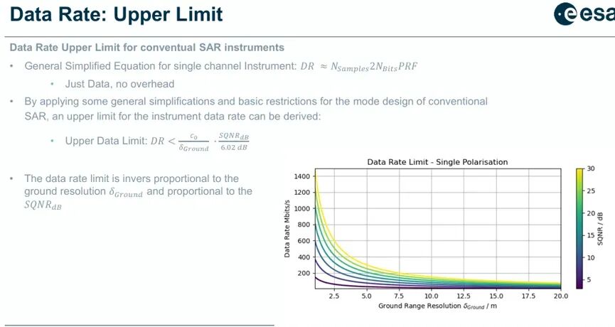
For conventional single-channel SAR instruments, the data rate can be approximated as:
Sample Bits
Through simplified derivation, the relationship between the upper bound of the data rate, ground range resolution , and quantized SNR can be obtained:
This formula reveals a fundamental constraint: the upper bound of the data rate is inversely proportional to resolution—doubling the resolution at least doubles the data rate. Technologies such as SCORE, MAPS, and FSCAN break this hard constraint through DBF, trading off performance in new dimensions.
6. New Space SAR: Commercialization Wave
In recent years, a large number of commercial SAR companies have emerged globally, driving the miniaturization, constellationization, and cost reduction of SAR platforms. Key players include:
Company Frequency Band Mass Cost per Satellite Planned Constellation Size Orbit Revisit Time Cost/Mass Ratio Capella Space (USA) X-band <40 kg <15 M$ 36 satellites (planned) 525 km 3-6 h 0.38 M$/kg Iceye (Finland) X-band 70 kg 10-15 M$ 18 satellites (in orbit) 575 km 3 h 0.21 M$/kg Synspective (Japan) X-band 150 kg 15 M$ 30 satellites (planned) 600 km 2-3 h 0.10 M$/kg Umbra Lab (USA) X-band 50 kg 3.5-5 M$ 12 satellites (planned) 515 km <1 h 0.10 M$/kg PredaSAR (USA) X-band 100-200 kg 75 M$ 48 satellites (planned) 425 km <4 h 0.38 M$/kg Trident Space (USA) X-band 300 kg 42-65 M$ 48 satellites (planned) ~500 km <1 h 0.22 M$/kg EOS SAR (USA) X-band 150 kg 15 M$ 6 satellites (planned) ~500 km 2-3 h 0.10 M$/kg
These commercial SAR systems exhibit the following trends: extreme vertical integration (complete in-house design, R&D, integration, testing, and launch), batch production to reduce cost per satellite, constellation deployment for hourly revisit, and potential for multistatic and distributed SAR applications. While these commercial systems cannot yet fully replace national missions like Sentinel-1 in terms of performance (resolution, radiometric calibration accuracy), their rapid iteration capabilities and business model innovations are profoundly reshaping the remote sensing data market landscape.
7. FPGA Digital Backend: From Sampling to Onboard Processing 7.1 Traditional Backend Functions and New Requirements
A typical radar digital backend comprises three major functional modules:
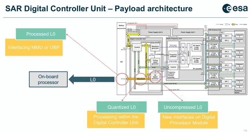
Waveform Generation: Direct digital synthesis (DDS), I/Q modulation, and upconversion; Timing Control: Coherent triggering and synchronization for transmission and reception; Digitization and Processing: Echo sampling, downconversion, digital processing, formatting, and scientific telemetry data generation.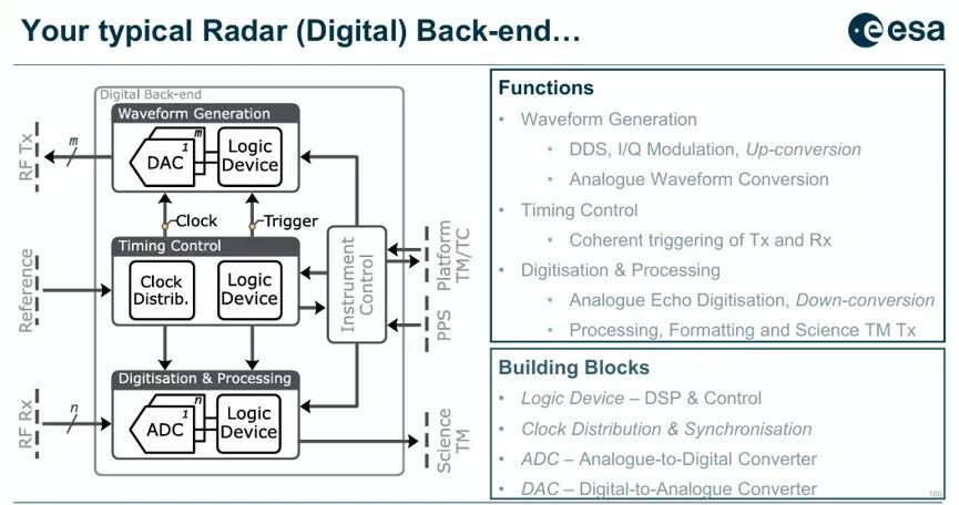
However, the demands of next-generation SAR missions are imposing far stricter requirements on the backend than traditional ones:
Direct RF Sampling: Requires ADC/DAC with direct conversion capability up to C-band (or even Ka-band); Multi-Channel Reception: Multiple RF receive channels per polarization (e.g., 20 channels for ROSE-L's 4 elevation × 5 azimuth), with sampling phase differences between channels controlled within picoseconds (<10¹² s) using advanced clock distribution and synchronization protocols like JESD204; Extremely High Data Rate: Scientific telemetry data rates reaching Gbps levels; Onboard Data Reduction: DBF operations, RFI detection, and resolution must be completed onboard to reduce downlink data volume.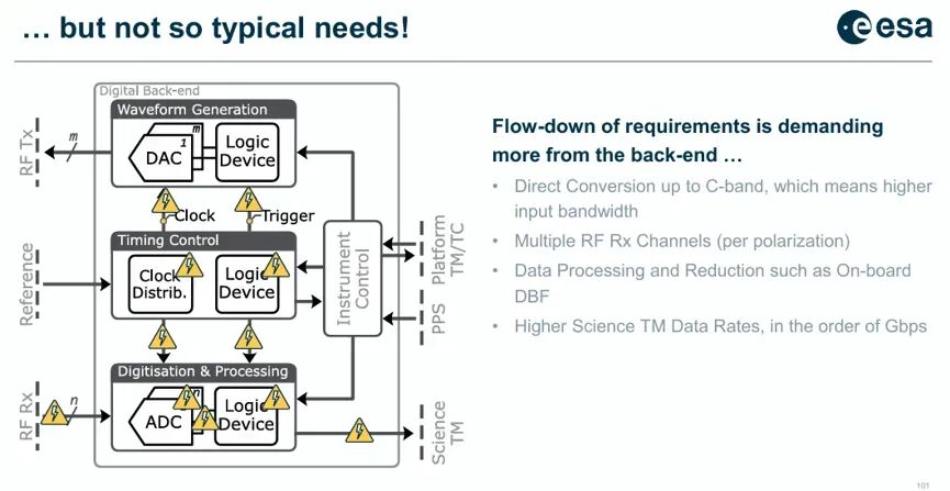
7.2 Challenges of High Sampling Rates and Logic Devices
The direct consequence of high sampling rates (typically 3.2 Gsps) is a surge in interface data rates. Countermeasures include:
Integrating digital downconversion (DDC) functionality within the ADC to reduce data rates from 30 Gbps to 3 Gbps (e.g., for L-band EO applications) through undersampling and downconversion;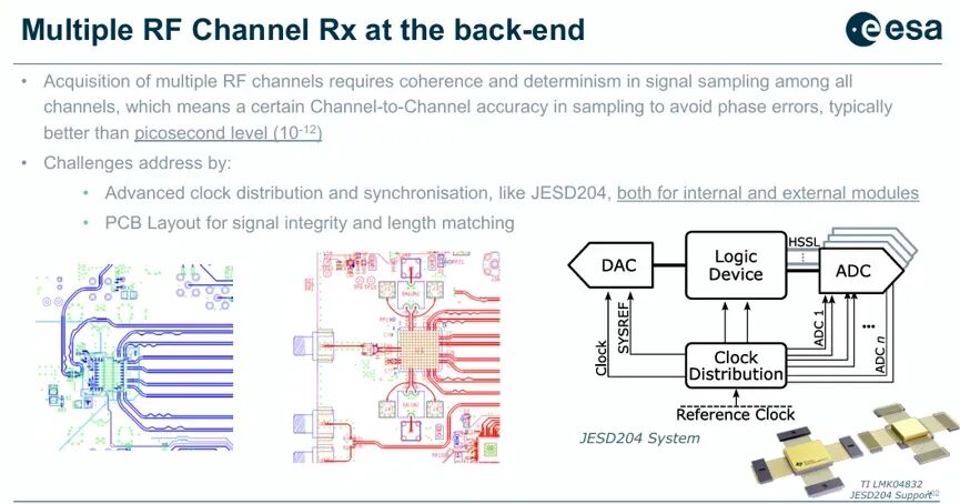
Employing high-speed serial links (HSSL) and JESD204 protocols to connect ADC/DAC with FPGA.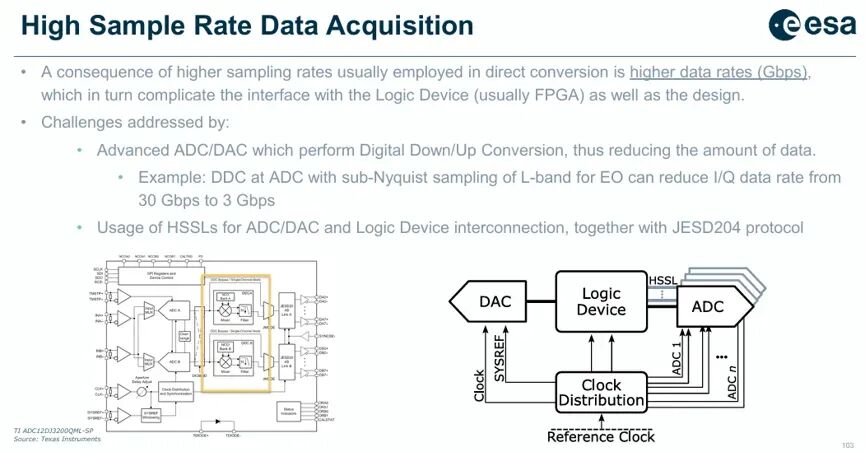
At the logic device level, space-grade FPGAs such as Xilinx Kintex Ultrascale, KU060, and Microchip PolarFire have been introduced, featuring powerful DSP capabilities and HSSL interfaces. However, engineering challenges remain prominent:
Susceptibility to radiation effects (SEE), necessitating single-event effect mitigation techniques (e.g., triple modular redundancy, dynamic refreshing) at the device level and availability analysis at the system level; Complex power distribution design—Xilinx Versal requires approximately 20 different power rails and must handle large current load transients; Higher demands on PCB process and assembly due to high-density packaging; Increased thermal design pressure—KU060 can consume up to 20 W in certain scenarios.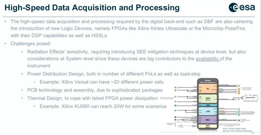
7.3 Latest R&D in European Industry
The UPM (Universal Processing Module) developed by Airbus Defence and Space represents the current advanced level of digital backends:
Based on space-grade Xilinx Ultrascale KU060 FPGA; Supports multi-channel digitization (both within and between modules); Direct conversion to C-band; 8 receive channels + 1 transmit channel; Maximum sampling rate of 3.2 Gsps; Integrates waveform generation, digitization, processing, and timing control functions within a single module, and supports embedded instrument control and application software.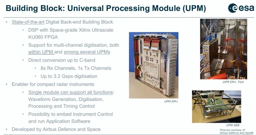
Thales Alenia Space (Italy) has developed a modular three-unit architecture:
First-Stage Processing Module (FSP): Echo acquisition and preliminary processing (based on Microchip PolarFire FPGA, 4 Rx channels per module); Second-Stage Processing Module (SSP): Data aggregation and advanced processing; Waveform Generator (WFG): Signal generation and control (1 Tx channel per module); Also supports direct C-band conversion and a maximum sampling rate of 3.2 Gsps.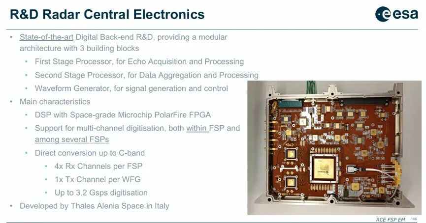 7.4 Future Backend Development Directions Higher Bandwidth: Extension to Ka-band direct sampling for enhanced software-defined radio capabilities; Smarter ADC/DAC: Integration of more DSP functions (DDC, DUC, digital predistortion) within the converter to offload FPGA burden; Faster Data Exchange Interfaces: To handle multi-channel Gbps-level data flows; Higher Integration: Further optimization of SWaP (size, weight, and power); Onboard Scientific Product Generation: Direct on-orbit completion of image focusing, classification, target detection, and RFI marking.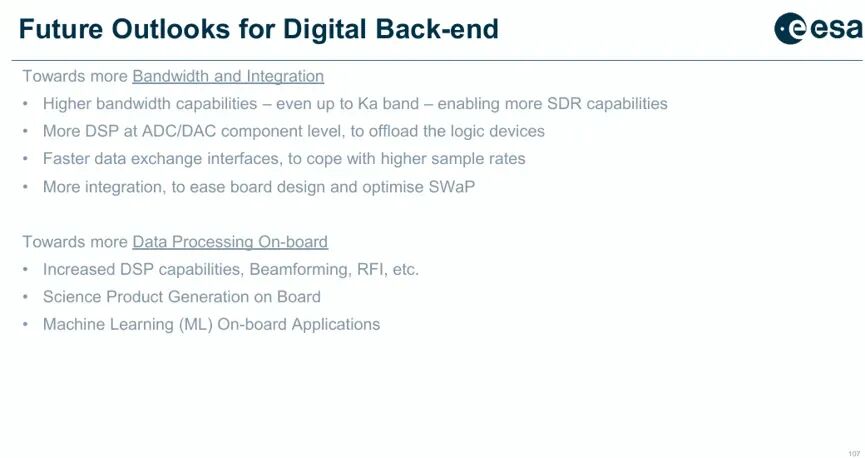
8. Cognitive Remote Sensing and Onboard Intelligent Processing 8.1 Definition and Value of "Cognitive"
"Cognitive microwave remote sensing" endows instruments with closed-loop capabilities for on-orbit perception, understanding, and response. Potential application scenarios include:
SAR: Rapid-response "tip-and-cue" systems—identifying moving icebergs, ships, or other targets and automatically guiding subsequent high-resolution observations; Microwave Radiometer: Real-time marking and classification of radio frequency interference (RFI), dynamically adjusting observation strategies or digital processing algorithms to avoid/eliminate interference; Precipitation/Meteorological Radar: Identifying key atmospheric phenomena and automatically switching to higher resolution and longer integration time modes to enhance scientific return; Radar Altimeter: Detecting mesoscale phenomena in sea surface height or catastrophic events (e.g., tsunami precursors) and triggering intensified observations.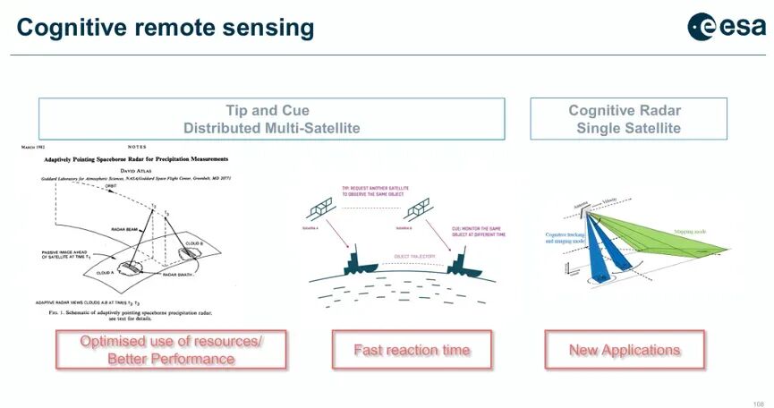
8.2 Practical Case: CIMR's Onboard RFI Processor
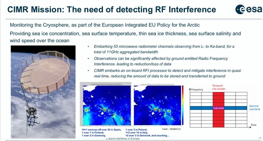
The Copernicus Imaging Microwave Radiometer (CIMR) mission exemplifies onboard intelligent processing. The mission carries 55 microwave radiometer channels, covering L-band to Ka-band, with a total aggregated bandwidth of 11 GHz. These observations are highly susceptible to ground-based RFI contamination (e.g., from radar and communication equipment emissions), making it unacceptable to downlink all raw data due to the enormous data volume.
The CIMR solution involves embedding a dedicated RFI processor onboard the satellite to perform interference detection and mitigation in orbit (including time-domain, frequency-domain, and polarization-domain detection algorithms), transmitting only "clean" observational data or RFI-tagged metadata downlink, significantly reducing downlink requirements and ground processing burden.
IX. Challenges and Future Prospects
Integrating the three threads of SAR system evolution, digital backend engineering, and cognitive intelligence, the core challenges facing spaceborne radar remote sensing in the next decade can be summarized as follows:
1. Data Explosion and Satellite-Ground Link Bottleneck: The data rate of new DBF SARs is more than 10 times higher than that of Sentinel-1 (4 Tbit/orbit vs. 0.4 Tbit/orbit). Relying solely on higher compression ratios cannot fundamentally solve the issue; onboard intelligent data screening and scientific product generation are required.
2. Complementarity and Competition Between Commercial and Institutional Missions: New space SARs offer hourly revisit times and flexible ordering, but their radiometric calibration and long-term stability are still difficult to match with the Sentinel series. Achieving interoperability and joint inversion of data from both is an important direction.
3. Radiation Tolerance of Digital Backends: The single-event effect sensitivity of advanced FPGAs (e.g., 7nm-class) has significantly increased, necessitating the construction of system-level radiation resistance from the process, design, and software perspectives.
4. New "Human-in-the-Loop" Paradigm for Cognitive Remote Sensing: The shift from "pre-programming-data downlink-ground processing" to "on-orbit sensing-autonomous decision-making-intelligent downlink" requires addressing regulatory issues related to algorithm reliability verification and mission safety.
5. Frequency Resource Constraints and Worsening RFI: More radar and communication systems are using similar frequency bands (especially L/C/X bands), making RFI an increasingly challenging issue that must be addressed through both onboard processing (e.g., CIMR) and spectrum management policies.
Conclusion
From ERS-1 to Sentinel-1, European spaceborne SAR technology has completed the transition from single-channel mechanical scanning to multi-mode active phased arrays. Currently, digital beamforming is opening the chapter of the fourth generation of SAR—technologies such as SCORE, MAPS, and FSCAN provide new solutions to the traditional trade-off between resolution and swath width, at the cost of a more than tenfold increase in data rate. Supporting this paradigm shift is the concurrent progress in high-performance digital backends (high-speed ADC/DAC, space-grade FPGAs, advanced clock distribution) and onboard intelligent processing (RFI suppression, scientific product generation, machine learning inference).
Meanwhile, the rise of new space commercial SAR constellations has injected a fresh rhythm and vitality into the remote sensing market. Looking toward 2030, the key themes of spaceborne radar remote sensing will be digitization (fully digital backends and DBF), intelligence (cognitive remote sensing and onboard processing), and commercialization (low-cost constellations and agile response)—working in synergy to build the next-generation Earth observation system.
References
The content of this paper is synthesized from the Earth observation section of the ESA/ECSAT 2023 report, "Satellite radio-frequency payloads and instruments Overview and challenges" (EDHPC 2023).
---
-
![]()
XR Business Rockets with 15-Fold Growth! Conant Optics Unveils 2026 Interim Report
-
![]()
Net profit surged by 186%! Accelink Technologies is cashing in on the AI computing power dividend
-
![]()
Trillion-Yuan Chip Project of Domestic Computing Power Behemoth Collapses!
-
![]()
Surging Over 536% Upon Listing! A New Laser Stock Yields Over 500,000 Yuan Per Lot
-
![]()
Keysight Technologies Releases Three Innovative Solutions for Design Engineering Software, Advancing Engineering Design into a New Era of Intelligence with Engineering Intelligence
-
![]()
Can the Robot Phone Propel Honor to New Valuation Heights?
-
![]()
Dealer Service Operation Capability | Constructing Four "Consciousness Firewalls" for Proactive Negative Public Opinion Management
-
![]()
Lenovo is Back in the Spotlight, This Time with Its 'AI for All' Story