Battery Energy Storage Series: An Overview of Battery Energy Storage System Components and Architecture
 01/30 2026
 648
648
Click to Follow and Stay Updated
Explore for More Technical Insights
This article spans approximately 2,700 words and is accompanied by 14 images.
Estimated reading time: 3-4 minutes
The preceding article in this series has already delved into the operational principles and distinctive features of various cutting-edge energy storage technologies, with lithium battery energy storage systems (BESS) dominating the installed capacity landscape. This article will now elucidate the core components, hierarchical structure, operational principles of battery energy storage systems, and also discuss the distinctions and application prospects of the two primary technical approaches: centralized and string configurations.
01 Battery Energy Storage System Composition and Key Equipment
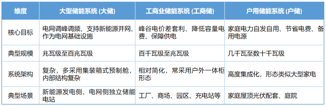
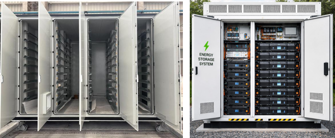
Based on application scenarios and scale, battery energy storage systems can be broadly categorized into large-scale storage (fixed building type, prefabricated cabin type), industrial and commercial storage (outdoor integrated cabinet), and residential storage (home storage).
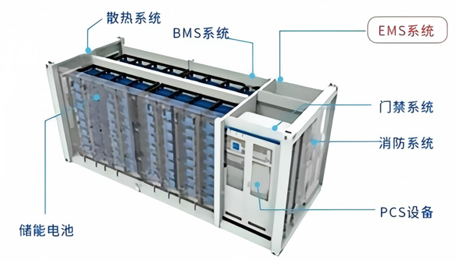
Residential storage systems are relatively straightforward and compact, whereas large-scale and industrial/commercial storage systems share a similar architecture. The fundamental components encompass: battery pack units, energy management systems (EMS), battery management systems (BMS), energy storage converters (PCS), and other equipment (auxiliary systems like containers, busbars, power distribution, temperature control, fire protection, video surveillance, lighting, and in-cabinet cables).
Mainly divided into four systems:
(1) Battery System
The battery system serves as the most pivotal module, responsible for the core functions of energy storage and release. Its performance directly influences the overall system efficiency. It typically adopts a multi-tier structural design: cell-module-battery pack-battery cluster-battery stack.
Battery Unit: A single cell, the smallest energy storage unit in the system, forms battery modules through series and parallel connections.
Battery Module: Comprised of tens to hundreds of battery units, featuring standardized packaging and interfaces.
Battery Cluster: Formed by connecting multiple battery modules in series, creating a storage unit with a specific voltage level.
Battery Stack: Formed by connecting multiple battery clusters in parallel, achieving megawatt-level storage capacity.
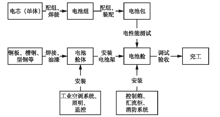
The battery system, along with other electrical and fire protection equipment, must be installed on a bearing platform that meets the physical and chemical protection requirements of the application site environment. It is generally categorized into two types: fixed building type and prefabricated cabin type, with the latter typically referring to container type and outdoor cabinet type.
(2) Battery Management System (BMS)
BMS acts as a crucial link connecting the battery and the user, responsible for real-time monitoring of the battery pack's performance and operational status, ensuring the safe and efficient utilization of the battery, and extending its service life. It generally includes a data acquisition module, protection module, balancing module, and communication module.
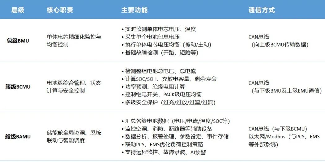
Given the large number of cells, containerized energy storage systems typically adopt a three-tier BMS management architecture:
①BMU (Pack-Level Management Unit)
As the lowest-tier monitoring unit, BMU is responsible for meticulous management at the individual cell level. It transmits the aforementioned information to the superior BMS in real-time via the CAN protocol and can control the voltage balance of individual cells.
②BCMU (Cluster-Level Management Unit)
As the intermediate-tier management unit, it is responsible for comprehensive management and control at the battery cluster level.
③BAMU (Cabin-Level Management Unit)
As the highest-tier management unit, it is responsible for the global coordination and system linkage of the entire energy storage cabin.
(3) Energy Storage Converter (PCS)
As another key piece of equipment in BESS, PCS accounts for approximately 20% of the total cabin cost, second only to lithium batteries (approximately 60%). PCS is primarily responsible for power conversion and control:
Bidirectional Conversion Function: Converts the battery's direct current (DC) into alternating current (AC) required by the grid and can perform the reverse operation when the battery is charging.
Charge and Discharge Control: Precisely controls the charge and discharge power and current according to system requirements, enhancing grid stability and system efficiency.
Grid-Connected/Off-Grid Switching: Supports seamless switching between grid-connected and off-grid modes (<10ms), ensuring continuous power supply to sensitive loads.
Power Regulation: Provides bidirectional regulation capabilities for active/reactive power, participating in grid frequency regulation, voltage stabilization, and other ancillary services.
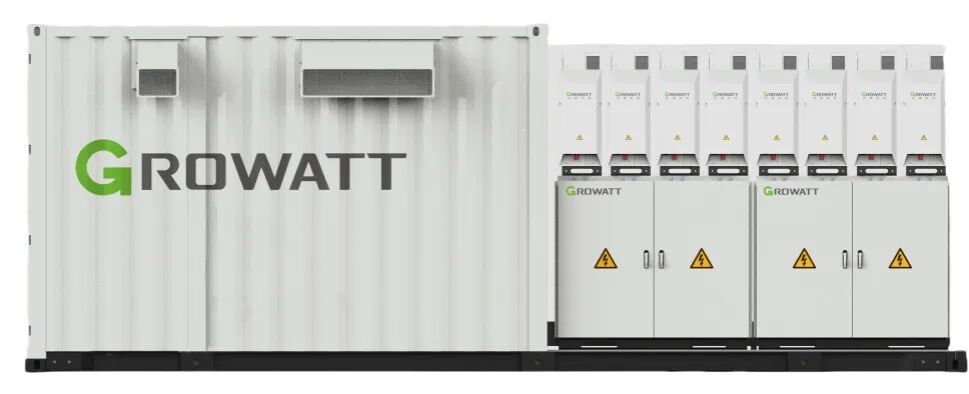
Large-Scale Storage Boost Converter Integrated PCS
The integrated forms of PCS mainly include two types:
① Boost Converter Integrated Design: Integrates PCS and the boost transformer in the same cabin, making the main components of the energy storage power station a "boost converter integrated cabin" + "battery container" form.
② Battery Converter Integrated Design: Integrates PCS and the battery container in the same cabin.
(4) Energy Management System (EMS)
EMS is a set of intelligent software and hardware systems that integrate monitoring, control, analysis, and optimization, specifically designed for energy system management. Through data acquisition from energy storage system equipment (PCS, BMS, meters, fire protection, air conditioning, etc.), data analysis and display, and energy scheduling, EMS controls the orderly and stable operation of the entire energy storage system.
In simple terms, EMS is the "brain" of the battery energy storage system, controlling and managing the stored electrical energy.
Data Acquisition and Analysis: Integrates data from BMS, PCS, the grid, and the external environment for real-time analysis and prediction.
Operation Strategy Formulation: Dynamically optimizes charge and discharge strategies based on information such as electricity price fluctuations, load demand, and renewable energy output.
Economic Optimization: Enhances system economics and reduces the levelized cost of energy storage (LCOS) through peak-valley electricity price arbitrage and ancillary service revenue.
Safety Protection Strategy: Formulates system-level safety protection strategies to ensure safe and stable operation under various working conditions.
(5) Auxiliary Systems and Electrical Equipment
Battery energy storage systems also encompass various auxiliary systems and electrical equipment to ensure safe and stable operation:
Thermal Management System: Controls battery temperature to prevent overheating or low temperatures from affecting battery performance and safety, such as Huawei's pioneering positive pressure oxygen barrier + directional smoke extraction joint defense mechanism.
Power Management System: Provides reliable power supply and protection for the system, equipped with high-performance surge protectors and UPS.
Fire Protection System: Prevents and responds to battery thermal runaway, such as the PACK-level perfluorohexanone fire protection system applied at Qinghai Hongliu Energy Storage Station.
Electrical Equipment: Includes AC panels, DC busbar cabinets, transformers, etc., to achieve reliable connections between the system and the grid.
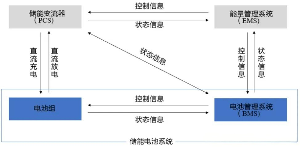
02 Battery System Architecture and Working Principle
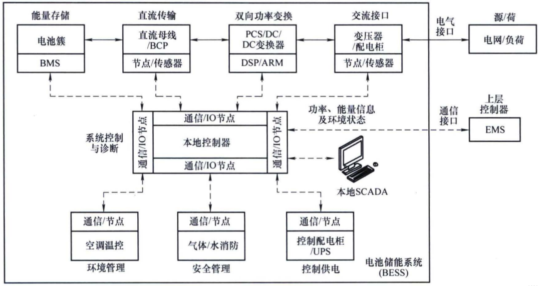
Taking the "peak shaving and valley filling" scenario as an example, the operational steps of the battery energy storage system are as follows:
Step 1: Grid Demand Perception (Control Layer)
The local controller receives EMS instructions: "High electricity prices from 14:00 to 18:00, discharge required."
Simultaneously, it receives BMS data: "Current SOC=75%, battery clusters 1-3 are in normal condition."
Step 2: Instruction Issuance (Control Layer → Execution Layer)
The local controller generates instructions: "Start PCS and discharge at 80% rated power."
Sends the instructions to PCS and BMS through the CAN bus.
Step 3: Power Conversion and Safety Coordination (Execution Layer)
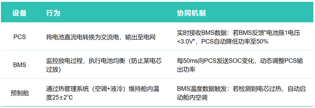
Step 4: System Closed-Loop Verification (Perception Layer → Control Layer)
BMS detects that SOC drops to 40% → sends a "discharge completed" signal to the local controller.
The local controller updates the EMS strategy: "Start charging during the low electricity price period (23:00-5:00)."
The system enters the next cycle.
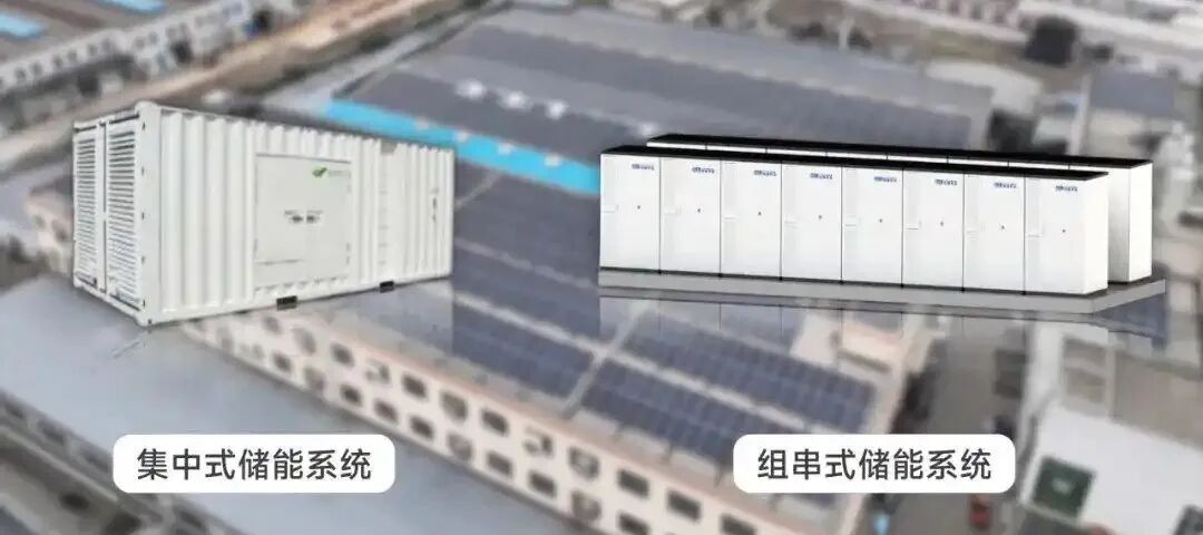
03 Centralized and String Architectures
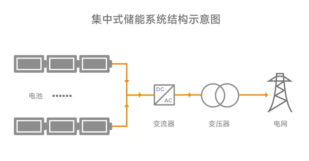
(1) Centralized Architecture
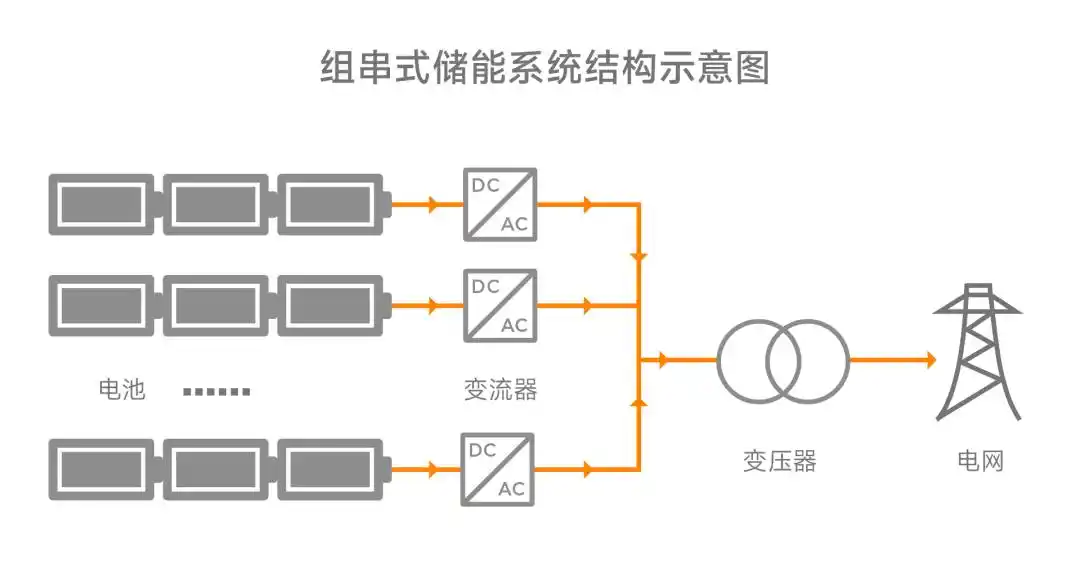
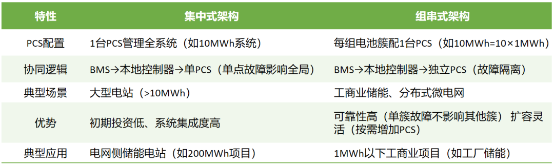
Centralized architecture is a commonly adopted solution for large-scale storage. Multiple battery packs are connected in parallel and managed uniformly by a centralized battery management system. Simultaneously, one or more PCSs are utilized to convert direct current into alternating current, which is then boosted by a transformer and connected to the grid.
Advantages:
Low Initial Investment: The unit cost of high-power PCS is lower, and the amount of DC-side equipment (busbar cabinets, cables, etc.) is minimal.
Small Footprint: Equipment is concentrated, suitable for scenarios with limited land resources.
Disadvantages:
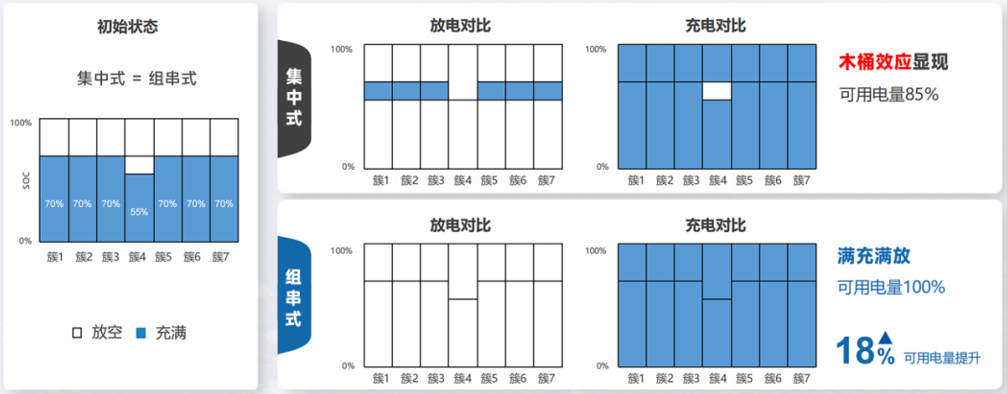
Severe "Bucket Effect": After battery clusters are connected in parallel, the current automatically balances. If the performance of individual cells or battery clusters declines, it will drag down the entire system's output capacity.
Difficult Operation and Maintenance: Fault location requires step-by-step troubleshooting, and shutdown for maintenance affects the overall system operation.
Poor Flexibility: Capacity expansion necessitates matching the PCS capacity, making it challenging to construct in phases.
(2) String Architecture
The battery pack is divided into multiple smaller "strings," each equipped with an independent BMS and string-level PCS. Each group is connected in parallel to the grid, and the overall system is coordinated and controlled by a central controller. It is suitable for distributed and modular application scenarios. The actual choice necessitates comprehensive consideration of factors such as project scale, investment budget, battery type, and operation and maintenance requirements.
Advantages:
No Bucket Effect: Each battery cluster operates independently, and performance differences do not affect each other, increasing the system's available capacity by 5-10%.
Intelligent Operation and Maintenance: Supports fine management at the cluster level, and faulty battery clusters can be isolated separately, enhancing operation and maintenance efficiency.
Flexible Expansion: Units can be added or removed as needed, adapting to the requirements of phased construction or capacity adjustment.
Disadvantages:
High Initial Cost: The large number of PCSs leads to increased equipment costs, and AC-side cables and protection equipment increase.
Slightly Larger Footprint: Decentralized layout requires more space.
Summary:
Disclaimer: Due to limited personal capabilities, if there are any errors, please point them out. This article is for learning purposes only. Some of the images and text used are sourced from the internet. If there are any copyright issues, please inform us promptly, and we will immediately delete them. No commercial use is intended!
-
![]()
Enflame Tech's IPO Journey: Navigating Over 5.9 Billion Yuan in Losses and Soaring Debt in Q1 This Year
-
![]()
Trillion-Yuan Giant Li Shufu 'Streamlines': Could Levc Be the Casualty?
-
![]()
AI Competes for Electricity and Generates Power in the Gobi Desert
-
![]()
The First Batch of Victims of the AI Bubble: Programmers
-
![]()
ByteDance, DJI, and Xiaohongshu Secure Top Three Positions Among China’s Fastest-Growing Unicorns
-
Tesla's in-car voice system in China is finally learning to 'understand human language'
-
![]()
Foreigners Are Amazed: Chinese Electric Vehicle Drive Systems Unveil Innovative 'Poses'
-
![]()
700,000 Brothers and the Future of Robots: Behind JD.com's 'Nirvana Plan'