
What are the Eight Redundancies for L3 Autonomous Driving in the Qijing GX7?
 09/29 2026
 484
484
Produced by Zhineng Technology
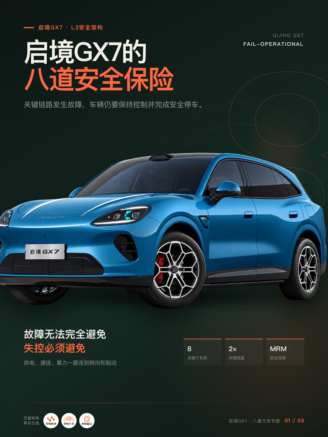
The Qijing GX7, designed for L3 autonomous driving, features redundancy across eight key areas: power supply, communication, computing power, perception, localization, steering, braking, and HMI interaction.
The scenarios that L3 redundancy must handle are those in which the vehicle is driving on behalf of the driver when a critical component suddenly fails. Unlike a smartphone freezing and shutting down, the vehicle must continue to perceive the road, calculate a safe trajectory, and control direction and speed, at least until a safe transition of control is completed or the vehicle enters a minimal risk state.
Redundancy ensures a safe conclusion after a fault occurs, rather than preventing the fault itself.
01 What Problems Does L3 Redundancy Solve?
Understanding this redundancy system begins with distinguishing between "architecture" and "function."
According to the national standard GB/T 40429-2021, L3 conditional autonomous driving means that within the designed operating conditions, the system performs all dynamic driving tasks; when the system issues a takeover request, the driver must take over within a reasonable time. The boundary between L2 and L3 does not lie in features like automatic lane changes or the presence of LiDAR, but in who bears responsibility for driving tasks.
In L2, the driver remains the primary operator, with the system providing assistance only. In L3, within defined conditions and timeframes, the system is the primary operator; if the system can no longer operate, a safe transition of control must be completed, or a minimal risk strategy must be executed.
Thus, having a "hardware architecture oriented toward L3" is only one of the necessary conditions for achieving L3.
The Qijing GX7 features a dual perception architecture, dual computing domain controllers, dual communication links, dual power supply architectures, multi-layered HMI, dual braking, dual steering, and dual localization. As leading-edge driving assistance cannot yet cover all road conditions, drivers must continuously observe the road and maintain active control.
The Qijing GX7 has the full-link redundancy hardware foundation for L3 development, but whether L3 functions can be enabled depends on specific vehicle approvals, regulations, software versions, and operational design domains.
The earlier model with the same architecture, the Qijing GT7, received approval for L3 road testing in specific scenarios in Guangzhou. Testing approval, product approval, and opening L3 to ordinary consumers are three distinct stages.
Many traditional automotive safety systems rely on fail-safe mechanisms, where a fault disables the function and alerts the driver. Since the driver is always in control, function deactivation itself represents a safe state. L3 is entirely different: when a vehicle is traveling at 100 km/h on the highway in L3 mode, the driver may be looking at a screen and not continuously monitoring the road.
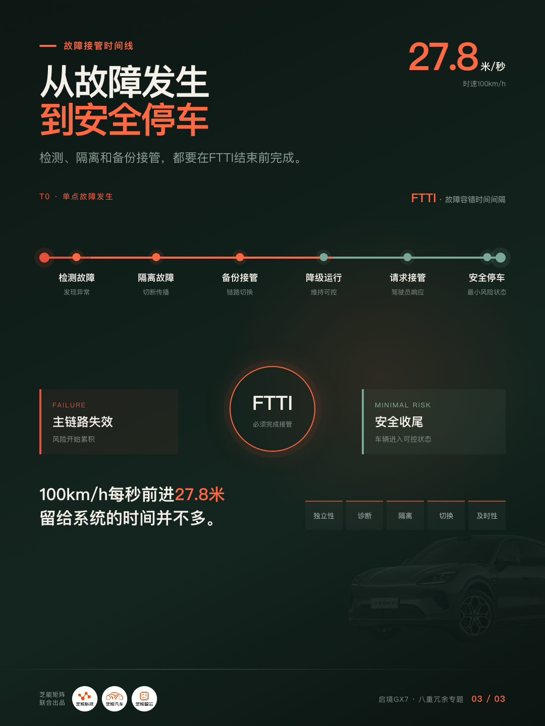
If the main computing platform suddenly restarts, the system cannot simply display a message saying, "Assisted driving has exited" and immediately transfer control of the steering wheel and brakes back to the driver. At 100 km/h—approximately 27.8 meters per second—even if the driver regains situational awareness in two or three seconds, the vehicle will have traveled tens of meters.
Therefore, L3 must evolve from fail-safe to a certain degree of fail-operational: after a fault occurs, the system may not provide a complete intelligent driving experience but must maintain safe operation.
This safety chain operates continuously: first, detect the fault and determine whether it affects safety functions; isolate the fault source; then switch to an independent backup link and enter a degraded operating state while issuing a takeover request and monitoring the driver. If the driver does not take over, execute a minimal risk strategy, ultimately entering a minimal risk state and recording the event.
The technical requirements for the Ministry of Industry and Information Technology's intelligent connected vehicle approval pilot program clearly state: the system should identify its own failures and, in the event of failure or insufficient functionality, continue to execute reasonable control until the vehicle enters a minimal risk state or is taken over. Functional safety must also consider the fault tolerant time interval (FTTI), safe state, emergency operation time, and functional redundancy.
The eight redundancy systems exist for this chain.
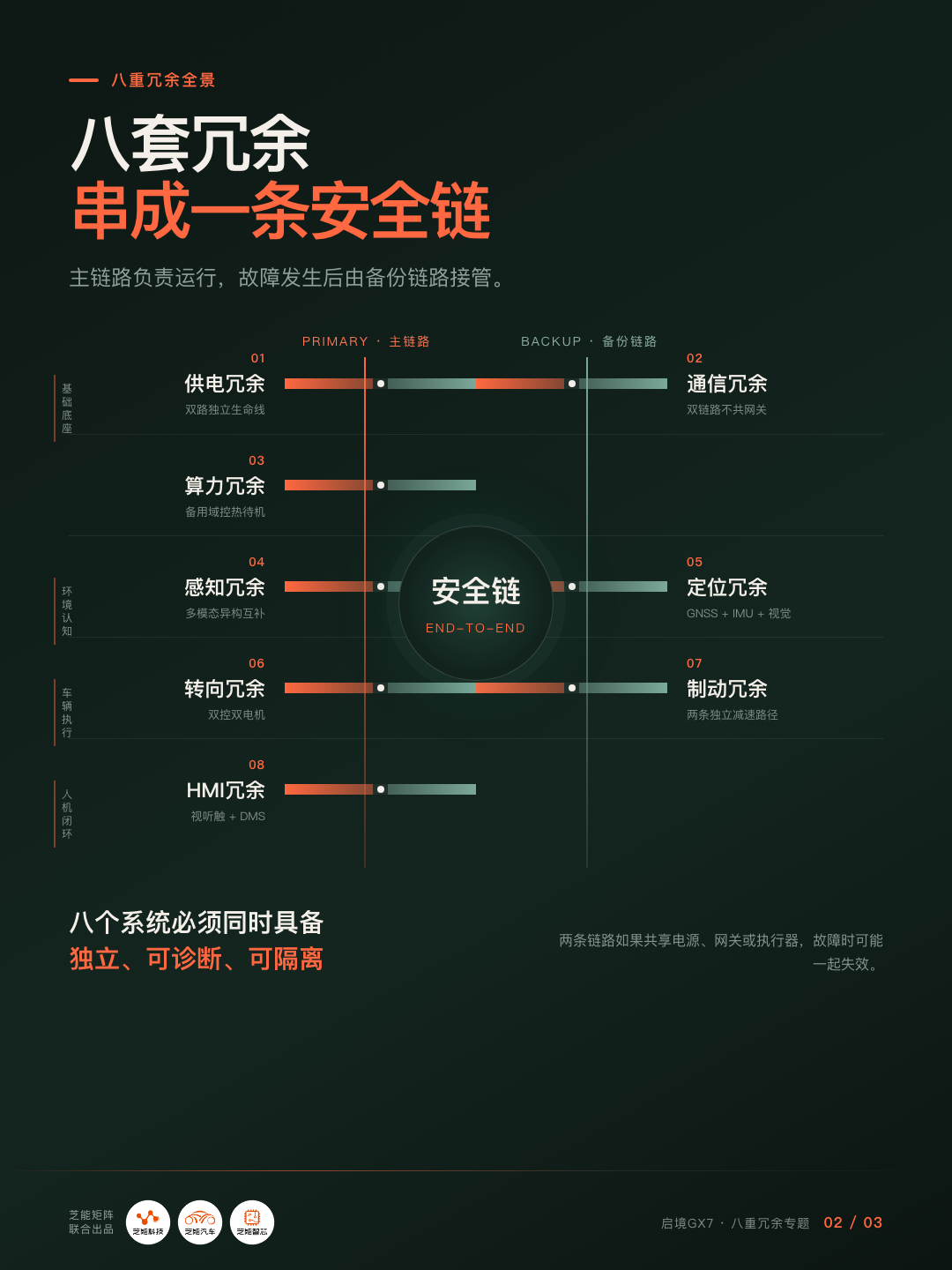
02 What Are the Eight Redundancies?
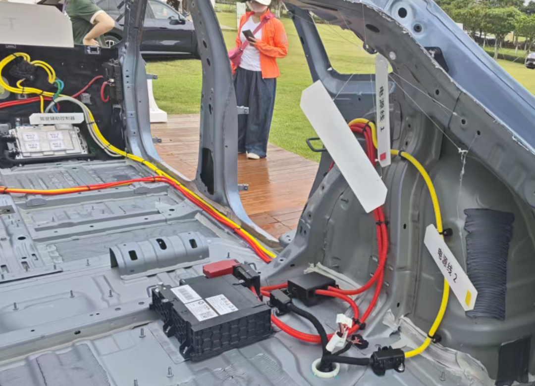
Power Supply Redundancy: Two isolated lifelines, not just two batteries
Autonomous driving relies on continuous power for sensors, domain controllers, in-vehicle networks, and steering and braking actuators. If any critical node loses power completely, all subsequent redundancies become meaningless.
Effective power supply redundancy requires independent low-voltage power paths, independent fuses and distribution, redundant DC/DC converters, backup power for key controllers, physically separated wiring harnesses, voltage anomaly monitoring and fault isolation, and the ability for low-voltage safety functions to persist for a time after a collision or high-voltage power cutoff.
The key is that the two power paths cannot be simultaneously disrupted by the same fault. If both paths share an upstream DC/DC converter, a common ground point, or the same wiring harness segment, a single short circuit, collision, or water ingress could still disable both paths simultaneously—this is called common-cause failure.
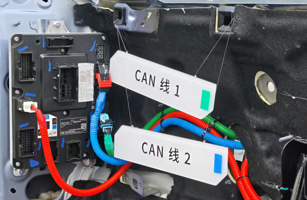
Communication Redundancy: Ensuring dialogue between "brain" and "limbs" after a fault
Domain controller-calculated steering and braking commands must reach actuators via the in-vehicle network, and sensor data must flow to the computing platform along the same network.
Communication redundancy involves dual CAN or CAN FD links, cross-backup between in-vehicle Ethernet and CAN, redundant gateways or switching chips, independent communication controllers, wiring harnesses with different physical paths, time synchronization and message integrity checks, and management of network congestion, packet loss, and bus abnormalities.
If one link is interrupted, congested, or flooded with abnormal messages, safety-related commands must still reach the braking and steering systems via another independent link.
Here too, common-cause failures must be prevented. If both links pass through the same central gateway, share the same power supply, or use the same software stack, a single gateway fault or software defect could still disable both links simultaneously.
Computing Power Redundancy: The backup computing platform is not for continuing "full-performance intelligent driving"
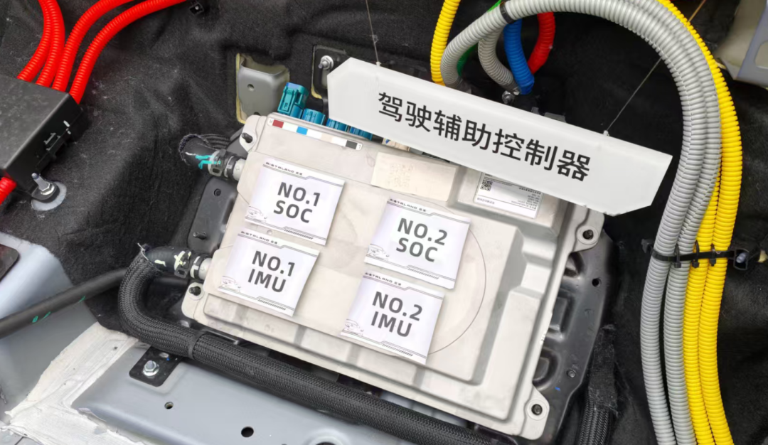
The Qijing GX7 officially describes its setup as "dual computing domain controllers," though public information does not disclose specific chips, computing power allocation, operating modes, or switching times for the two domain controllers.
Computing redundancy generally takes several forms: dual platforms running simultaneously for mutual verification, a primary platform running full functionality while a backup platform remains in hot standby, a primary platform handling full intelligent driving while a safety controller runs only simplified safety functions, or two platforms dividing tasks and reconstructing functionality after a fault.
For L3, the backup computing platform's most critical task is not to continue urban piloting, automatic overtaking, or comfortable lane changes but to maintain a strictly verified safety core: continue reading necessary sensors, judge the vehicle's lane and surrounding obstacles, generate a conservative trajectory, stabilize deceleration, perform a safe lane change if necessary, activate hazard lights, and ultimately stop the vehicle. This represents degraded operation, not seamless switching of original functionality.
Two computing platforms do not equal two independent brains. If both platforms use the same algorithms, training data, and software code, a systemic software defect could cause both to fail simultaneously. Therefore, high-level computing redundancy involves not just redundant hardware but also independent monitoring, safety islands, abnormal result comparisons, and even heterogeneous hardware or diversified algorithms for parts of the safety chain.
Localization Redundancy: Not "always precise even without signal"
Autonomous driving localization relies on multiple information sources: GNSS or high-precision satellite positioning, IMU inertial measurement, wheel speed and steering angle estimation, visual positioning, LiDAR-to-map matching, and road feature-to-lane line matching.
The core of dual localization assurance is that when satellite signals are obstructed by tunnels, tall buildings, or other blockages, the vehicle can still maintain positioning for a time using inertial, wheel speed, and environmental features.
Both inertial navigation and wheel speed estimation accumulate errors over time, reducing positioning confidence the longer they operate. Safe localization redundancy should simultaneously output two results: where the vehicle most likely is, and how confident the system is in that position.
Once positioning error exceeds a safety threshold, the vehicle should limit functionality, reduce speed, or enter a minimal risk strategy rather than continue "confidently driving" in the wrong location.
Perception Redundancy: Focus on "heterogeneous complementarity"
The Qijing GX7's official configuration lists 38 assisted driving sensors: one 896-line dual-optical-path imaging LiDAR, three high-precision solid-state LiDARs, five 4D millimeter-wave radars, eleven high-perception cameras, twelve ultrasonic radars, and six exterior microphones.
A dual-optical-path LiDAR uses two optical paths within a single radar. The GX7's four-LiDAR setup consists of one forward-facing dual-optical-path radar plus three solid-state LiDARs.
Effective perception redundancy must simultaneously satisfy three conditions: different modalities (cameras, LiDAR, and millimeter-wave radars operate on different physical principles); complementary coverage (no critical blind spots in forward, lateral, or rear directions); and algorithm-based conflict identification (when cameras indicate an empty space ahead but radars detect an object, the system must recognize the discrepancy).
Cameras excel at color, lane lines, and semantics; LiDAR excels at 3D distance and contour; millimeter-wave radars have advantages in speed measurement and operation in rain or fog. The value of multi-modal fusion lies precisely in their unlikely simultaneous failure in identical ways.
More sensors do not guarantee absolute perception reliability. Mud or water could simultaneously obscure multiple sensors; heavy rain degrades camera and LiDAR performance; strong reflections, multipath effects, and unusually shaped construction obstacles can also cause misjudgments.
Therefore, L3 perception systems must also estimate their own "perception confidence." When the system is uncertain whether it has clearly perceived the road, the correct approach is to contract the operational design domain (ODD), reduce speed, and if necessary, exit autonomous driving.
Steering Redundancy: Maintaining basic lateral control after primary steering failure
Even if the autonomous driving system perceives the road and calculates a trajectory, it cannot complete a safe stop if it cannot turn the steering wheel.
Steering redundancy may include dual controllers, dual motors or windings, dual position sensors, independent power supplies and communication, mechanical steering pathways, and limited steering capability after a fault. The goal is not necessarily to continue aggressive obstacle avoidance after a fault but to ensure the vehicle can stably maintain its lane, correct direction, and pull over when safe conditions allow.
It is important to note that if dual steering controllers still share a single motor, rack, mechanical connection, or power supply, they can only cover certain electronic faults; mechanical-level steering failures may still penetrate the redundancy.
Braking Redundancy: At least two independent means of generating deceleration
Nearly all final actions after a severe L3 vehicle fault involve deceleration and stopping.
Braking redundancy may be achieved through various systems working together: integrated electronic braking, electronic stability control, independent hydraulic circuits, drive motor regenerative braking, electronic parking brake, and independent brake controllers with pressure sensors.
High-quality braking redundancy cannot rely solely on "having two controllers." It must also consider how much deceleration the backup path can generate after primary system failure, whether it supports stable control of left and right wheels, and whether it can operate during vehicle power loss or communication interruption.
Motor regenerative braking can provide auxiliary deceleration but cannot replace mechanical braking under all vehicle speeds, battery states, and road conditions. The electronic parking brake can also serve as a final fallback but is unsuitable as the primary braking method at high speeds.
The essence of redundant braking is ensuring at least one independent, controllable, and verified deceleration link.
HMI Interaction Redundancy: This is the "responsibility handover chain"
HMI redundancy differs from the previous seven categories; it serves as the safe channel through which the system transfers driving tasks back to the driver.
When the L3 system issues a takeover request, it must confirm whether the driver has seen or heard the request, whether they are currently capable of taking over, and whether they have regained vehicle control.
Visual, auditory, seat, or seatbelt haptic alerts reduce the probability of a single warning being ignored, but multiple warnings do not guarantee driver response. Therefore, driver monitoring systems (DMS) are also necessary.
If the driver is asleep, unconscious, or continuously unresponsive, the system cannot indefinitely escalate alerts but must transition to a minimal risk strategy.
L3 systems must incorporate driver takeover capability monitoring. The new mandatory national standard GB 44721-2026, released in July 2026 and scheduled for implementation on July 1, 2027, explicitly requires system state indication, takeover capability monitoring, minimal risk strategy execution, and user role transition functions.
03 From Single-Point Redundancy to Full-Link
A vehicle may have dual chips, dual communication networks, and dual braking controllers yet still lack reliable L3 redundancy.
Autonomous driving safety operates as a series system: power supply, perception, localization, computing, communication, steering and braking, and HMI are interlinked. If any critical link contains an intolerable single-point failure, the entire safety chain breaks.
For example, a backup computing platform exists, but it shares a power supply with the primary platform. Two communication networks exist, but both pass through the same central gateway. Multiple sensors exist, but all data flows to a single domain controller. Two braking control logics exist, but they share an actuator that cannot be isolated. The system can still control the vehicle but cannot issue an effective takeover request. All hardware functions normally, but a software update introduces the same error in both systems simultaneously.
Redundancy design must simultaneously satisfy five conditions:
◎ Independence ranks first: primary and backup systems must not be simultaneously compromised by the same power supply, wiring, gateway, software defect, or environmental factor.
◎ Diagnosability ranks second: the system must first identify what fault has occurred in the primary system. If it cannot detect the fault, the backup will not know when to take over.
◎ Fault isolation ranks third: upon detecting an anomaly, the system must prevent the fault from propagating further. A short circuit must not take down the backup power supply, and a faulty node must not continuously send erroneous instructions to the bus.
◎ Timeliness ranks fourth: the interval between fault occurrence and backup link establishment of control must be shorter than the system's allowable fault tolerant time interval (FTTI). Whether "millisecond-level takeover" is achievable cannot be judged solely by claims but must consider specific fault types, detection time, isolation time, and control authority switching time.
While traveling at 100 km/h within a highway-limited ODD, if the primary computing platform suffers an irrecoverable fault, the theoretical safe handling process is as follows:
The safety monitoring module first identifies that primary computing results have stopped updating or become abnormal. Within the FTTI, the system confirms the fault to avoid erroneous switching, then isolates the primary computing platform from the communication network. The backup computing platform takes over necessary perception, localization, and control functions. Backup power supply and communication links ensure continued transmission of safety control instructions. The vehicle maintains its lane and begins a smooth deceleration. Visual, auditory, and haptic channels simultaneously issue a takeover request. DMS judges whether the driver has regained attention and taken over;
The driver does not respond, and the vehicle implements a minimum risk strategy, pulling over when it is safe to do so. If safe lane-changing conditions are not met, the vehicle will decelerate and stop within the lane. Finally, the hazard warning lights are activated, and the fault, takeover request, and vehicle control process are recorded.
The United Nations UN R157 requirements for minimum risk maneuvers specify that the vehicle should decelerate safely within the lane or, if the system has lane-changing capability and current conditions permit, stop outside the driving lane. Forcing a pull-over becomes more dangerous when there is a vehicle on the right, road construction, no shoulder, or degraded perception capabilities.
The full-link redundancy architecture of GT7 has passed specialized site testing by the China Automotive Technology and Research Center (CATARC) and completed over 200 real-world road scenario tests.
The redundancy system must verify scenarios including sudden interruption of single-power supply, primary domain controller power-off restart or abnormal output, severance of CAN or Ethernet links, camera obstruction, LiDAR performance degradation, GNSS signal loss or error, primary steering controller failure, and primary braking controller failure.
It must also cover scenarios where the driver does not respond to takeover requests, multiple related faults occur simultaneously, and cascading faults triggered by voltage fluctuations, network congestion, and sensor degradation.
It must also answer questions such as how long it takes to identify a fault, whether the primary-backup switch produces sudden changes in direction or braking, how long the degraded state can be sustained, under what conditions the system determines it is safe to change lanes, whether minimum risk maneuvers can still be completed after multiple consecutive faults, how latent faults in the backup system can be detected through power-on self-tests and periodic diagnostics, whether the system can revert to a safe version after a software upgrade failure, and whether faults and takeover processes are fully recorded.
ISO 26262 primarily addresses random hardware faults and systemic development defects in electronic and electrical systems, while ISO 21448 focuses on risks arising from insufficient perception or algorithmic capabilities despite intact hardware.
The latter is particularly applicable to L1-L5 systems relying on complex sensors and algorithms. Therefore, L3 safety certification must comprehensively cover functional safety, expected functional safety, cybersecurity, data and event recording, human-machine interaction, software update safety, ODD boundary identification, as well as real-vehicle, site, and simulation verification.
Summary
The Qijing GX7 represents a collaboration between GAC Group and Huawei to integrate post-autonomous-driving-failure control capabilities into the vehicle's foundational architecture from the early development stages. The L3 architecture primarily addresses what the vehicle can still do when system anomalies occur.
The key challenge for L3 is ensuring the vehicle knows how to stop safely when the driving system suddenly malfunctions.
-
![]()
Save up to 12,000 RMB in Car Purchase Subsidies: Here's What You Need to Know
-
![]()
NIO and Geely Forge a 'Strategic Alliance'
-
![]()
Shenlong Technology Achieves in Just Over a Month What a 40-Year Joint Venture Couldn't
-
![]()
New Energy Vehicles Face a 'Scale Dilemma': Wan Gang and Zhu Huarong Offer Solutions!
-
![]()
What are the Eight Redundancies for L3 Autonomous Driving in the Qijing GX7?
-
![]()
Can Huawei’s Four ‘Jie’ Brands Maintain AITO’s Momentum? Who Will Lead the Charge?
-
![]()
Can Yi Jing and Qi Jing Replicate Aito's Triumph and Achieve Blockbuster Status with Major Automakers and Huawei?
-
![]()
Sunway Communication Doubles Down on High-End MLCC Amid Net Profit Decline, Despite Target's Losses and Domestic Breakthrough Challenges