Why is there a black hole in the middle of LiDAR point clouds for autonomous driving?
 02/28 2026
 533
533
Have you ever noticed a phenomenon when observing the point clouds detected by LiDAR? That is, there is a circular 'vacuum zone' at the center of the three-dimensional point cloud image.
No matter how complex the traffic environment around the vehicle is, there is a hollow area without any data points distributed within a few meters around the car's chassis and body in the point cloud map.
This phenomenon is not due to sensor failure, nor is it because the laser cannot illuminate the ground. Instead, it is an inevitable result caused by multiple factors, including the physical characteristics of LiDAR, installation geometric limitations, optical transceiver architecture, and backend algorithm processing logic.
The size of this 'blind zone' directly affects the vehicle's perception of near-field obstacles such as curbs, low pets, or debris scattered on the road.
Physical Boundaries of Vision and Constraints of Installation Geometry
The main reason why LiDAR cannot generate point clouds near the vehicle body is the physical angular limitation of its vertical field of view. Current vehicular LiDAR, especially traditional mechanically rotating radars, do not emit laser beams in a global spherical coverage but rather within a specific vertical field-of-view range.
Take a common vehicular mechanical radar as an example; its vertical field of view typically ranges from 30 to 40 degrees, and these beams are distributed at certain angles upward and downward from the horizontal plane.
When the radar is installed on the roof, approximately 1.8 to 2 meters above the ground, there is a significant angle between the lowest laser beam and the normal to the vertical ground.
According to basic triangular geometry, lasers propagate in straight lines. During the process of the lowest laser beam shooting toward the ground, since its emission angle cannot be vertically downward, an inverted conical shadow area that cannot be covered forms below the radar before the beam touches the ground.
If the LiDAR is installed at the center of the roof and the downward deviation angle of its lowest scanning line is insufficient, a ground blind zone with a radius of several meters will appear around the vehicle. Within this area, any object with a height lower than the laser beam path cannot generate a reflected signal.
For passenger vehicles, if the installation height is around 0.8 meters and no special tilted installation measures are taken, the first detection point on the ground ahead may appear beyond 3 meters. This means that ground information within 3 meters directly in front of the bumper will be completely missing.
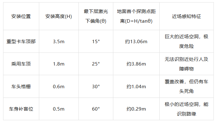
Theoretical Blind Zone Distances Under Different Configurations
Besides height and angle, the vehicle's own occlusion is also an important factor leading to the hole. Since LiDAR is installed on the roof or front of the vehicle, its scanning path will inevitably be blocked by the roof edge, hood, or rearview mirrors.
To prevent these fixed vehicle structures from causing interference in the point cloud, engineers will define an 'ego-vehicle filtering zone' within the radar's scanning range based on the vehicle's physical contour.
Any points falling within this area, even if they truly exist, will be directly removed by software algorithms during the data preprocessing stage, further amplifying the sense of emptiness in the point cloud map.
Detection Blind Zones Caused by Optical Transceiver Architecture
Besides the installation position, the internal optical transceiver design of LiDAR also determines that it will have a physical minimum detection distance. The core of LiDAR's operation is the Time-of-Flight (ToF) principle, which calculates distance by measuring the time difference △t between laser pulse emission and reception of reflected light, expressed by the formula R = c × △t/2, where c is the speed of light.
Over very short distances, this time difference is extremely small, posing stringent requirements on the sensor's electronic response speed. If an object is too close to the radar, the round-trip time may be shorter than the physical time required for the detector to switch from emission to reception state, resulting in the signal being unable to be captured.
The optical architecture of LiDAR mainly falls into two forms: coaxial (Monostatic) and off-axis (Bistatic). In a coaxial design, the emission and reception optical paths share the same optical aperture.
Theoretically, a coaxial system can achieve detection from zero meters, but in practice, the enormous optical energy at the moment of emission produces weak scattering on internal optical elements. This scattered light directly enters the highly sensitive detector, generating internal echoes and causing the detector to be in a transient saturation or blind state at the moment of emission.
To protect the circuit and eliminate interference, the system must set a short time window to block (Note: ' block ' means 'shield' or 'block'; consider replacing with 'block') signals during the initial emission period, physically creating a detection blind zone of about 10 to 20 centimeters.
The off-axis architecture design is more complex, with its emission and reception lenses physically separated, similar to human eyes.
Only when an object is located beyond a certain distance can the emitted laser spot enter the effective field of view (FOV) of the reception lens, a phenomenon known as geometric overlap.
At extremely close ranges, the reflected light spot completely falls within the blind zone of the reception lens, and the detector cannot perceive the signal at all. The minimum effective range of off-axis LiDAR is limited by the distance and convergence angle between the two lenses, resulting in its inability to generate reliable point clouds within 0.5 meters or even closer.
In addition, laser detectors (such as avalanche photodiodes APD or single-photon avalanche diodes SPAD) themselves have a certain recovery time.
After capturing a pulse, the detector needs a period of reset time before it can respond to the next signal again. For SPAD detectors, this recovery time (Rest Time) is generally between 400 nanoseconds and 1 microsecond.
This means that if the reflected light from a nearby obstacle arrives before the first emitted pulse has dissipated, the detector will not be able to respond to it. This electronic-level delay explains on a microscopic scale why the point cloud is inevitably missing in areas close to the radar window.
Strong Light Saturation and the Processing Limits of Electronic Circuits
In actual road environments, since the intensity of reflected light decays with the square of the distance, the laser energy intensity returned from near-field objects is extremely high, far exceeding the sensor's dynamic range.
When an object with high reflectivity (such as a reflective vest, clean license plate, or white car paint) appears within a few centimeters to one or two meters of the radar, the optical power received by the detector may be several orders of magnitude higher than when detecting objects hundreds of meters away.
This extremely strong signal can cause the transimpedance amplifier (TIA) in the reception circuit to instantly enter the saturation zone.
Once the amplifier is saturated, the signal waveform it outputs is no longer a clear narrow pulse but is flattened at the top and undergoes severe pulse broadening.
From the perspective of the time measurement circuit, this distorted waveform is difficult to accurately count and may even be misjudged as background noise or interference signals.
For some lower-performance LiDARs, this saturation effect can cause near-field obstacles to appear as 'holes' or flickering phenomena in the point cloud, making it difficult for perception software to establish continuous tracking logic. This, in turn, may lead to for no reason (Note: ' for no reason ' means 'unexplained' or 'without reason'; consider replacing with 'unexplained') jerking or sudden braking during vehicle operation.
To address this saturation issue, technologies such as multi-threshold detection, automatic gain adjustment, and saturation waveform compensation algorithms have been developed to attempt to recover true distance information. However, under extreme close ranges, the convergence of optical energy can still produce physical-level interference.
In addition, if multiple autonomous vehicles encounter each other at close range, the laser pulses emitted by each vehicle may cause mutual interference in the other's near-field area, leading to increased noise and forcing the system to filter out more unreliable data through algorithms. This further enhances the visual characteristic of a 'hole' near the point cloud.
Software-Level Ego-Vehicle Shielding and Redundant Perception
After understanding the limitations at the physical and electronic levels, we also need to examine one of the most critical steps in the autonomous driving system: ego-vehicle point cloud filtering.
When LiDAR is scanning at full speed, its field of view will inevitably include vehicle components such as the roof rack, hood edge, or trunk contour scanned by the rear radar.
If left unprocessed, these fixed metal or plastic surfaces will generate high-density point clouds, visually appearing as if the vehicle is wrapped in a thick layer of debris.
These 'ego-vehicle points' are not only meaningless for perception but also cause serious interference to target recognition algorithms.
To solve this problem, the autonomous driving perception system will define a restricted zone in the radar coordinate system based on a high-precision three-dimensional CAD model of the vehicle.
Any three-dimensional coordinate points located within this restricted zone will be completely erased by filtering algorithms (such as pass-through filters or crop filters) before the data enters the perception decision-making layer.
This algorithmic processing is the most direct driver of the regular blank space at the center of the point cloud map. Since the filtering zone is usually a few centimeters larger than the actual vehicle body to accommodate errors caused by vibrations, there is always a vacuum zone surrounding the vehicle in the point cloud map.
Current autonomous driving technology is further reducing this hole through hardware-level innovations. For example, some new 'short-range LiDARs' adopt an ultra-wide-angle design, with their minimum detection distance compressed to 5 centimeters or even lower.
By embedding these small sensors at the four corners of the vehicle body, the system can achieve true omnidirectional three-dimensional coverage, filling the originally empty point cloud center with real ground details and obstacle contours.
Final Words
The hole appearing in the center of LiDAR point clouds is a compromise that LiDAR must make to ensure data accuracy when facing extreme changes in physical geometry, optical paths, and electrical signal intensity.
For the perception system, understanding and accepting this hole and filling it through multi-sensor fusion is the technological cornerstone for ensuring the safe navigation of autonomous vehicles in complex urban roads.
-- END --
-
On the Eve of Its IPO, Avatr Finds Itself Embroiled in a 'Farce of Controversy and Belittlement'
-
![]()
Yutong Optics' Japanese Subsidiary Unveiled in Tokyo, Shifting Strategic Focus to Technology-Driven Growth
-
![]()
Half-Year Revenue Outstrips Last Year’s Total! Zhongrun Optics Forecasts 80.2% H1 Revenue Growth
-
![]()
Why Does AI Competition Start with Computing Power?
-
![]()
Apple AI Finally Makes Its Debut in China, Yet iPhone's 'AI Autonomy' Faces Uncertainty
-
![]()
Apple AI and QianWen Make Up Lessons: Alibaba Has Its Own 'Doubao Phone'
-
![]()
QianWen Joins Apple, Signal for Large Models to ‘Fade into the Background’
-
![]()
The ‘Anchor’ Strategy of Google Hidden Behind the Bleeding Financial Report